Quick Answer: What Should OEM Buyers Check First?
A Battery Thermal Management Temperature Sensor should provide temperature feedback at the location the battery management system actually needs to monitor, while remaining electrically compatible with the BMS measurement circuit and mechanically stable in the battery assembly. Buyers should evaluate R25, B value and the full resistance-temperature curve, sensing position, thermal contact, response behavior, sensor thickness or probe geometry, wire and connector design, environmental exposure, sample validation and production consistency. The sensor supports monitoring and thermal-control decisions; it should not be treated as a stand-alone device that prevents thermal runaway.
Why Temperature Sensing Matters in Battery Thermal Management
Battery packs do not operate at one uniform temperature. Cells close to cooling channels, enclosure walls, busbars or heat-generating components can experience different thermal conditions, while charging, discharging, ambient temperature and cooling-system operation can change the temperature distribution over time. For an EV, hybrid or energy-storage OEM, the challenge is therefore not simply to “measure battery temperature.” The real engineering task is to measure the temperatures that are meaningful to the BMS and thermal-management strategy.
Tianrui’s existing NTC application content identifies battery thermal management in EV and hybrid systems as an NTC sensing application, with sensors used within battery packs to monitor cell or module temperature. Its broader NTC temperature sensor guide also lists battery thermal management among automotive and EV temperature-sensing requirements. The important sourcing point is that an NTC sensor provides temperature-dependent resistance data; how the BMS interprets that information and responds to it belongs to the complete battery-system design.
What Is a Battery Thermal Management Temperature Sensor?
A Battery Thermal Management Temperature Sensor is a sensing component installed at a defined point in a battery pack, module, thermal plate, coolant circuit or related assembly to provide temperature information to the battery management or thermal-control system. NTC thermistors are commonly suitable for this role because their resistance decreases predictably as temperature rises, allowing the BMS electronics to derive temperature from the measured resistance.
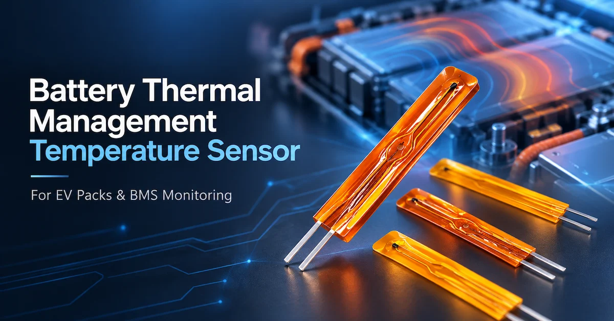
The finished sensing component can take several forms. A low-profile sensing element can be placed where installation space is limited; a wired NTC assembly can provide a controlled electrical interface to the BMS; and a metal probe may be appropriate where the measurement point is associated with a coolant path or another mechanically protected location. Tianrui’s product structure separates NTC thermistor elements from assembled NTC temperature sensors, which is an important distinction for OEM sourcing: selecting an NTC element is not the same task as qualifying the complete installed sensor assembly.
Where Should Battery Temperature Sensors Be Located?
Sensor location should be chosen around the thermal question the BMS needs to answer. A sensor attached to a cell surface does not measure exactly the same condition as one located between modules, on a busbar, inside an enclosure or in a coolant circuit. More sensors do not automatically produce better thermal information if their positions do not represent the important thermal zones of the pack.
For direct or near-cell monitoring, thin and low-mass sensing structures can reduce packaging interference and can respond closely to the local surface condition when installed correctly. For module-level monitoring, the sensing point should represent the thermal behavior the control strategy is intended to track. A coolant-line sensor provides information about the thermal-management circuit rather than direct cell temperature. These measurement points can complement each other, but they should not be treated as interchangeable.
A useful OEM drawing should therefore identify the sensor position, attachment method, orientation and surrounding materials. If engineering approves a sensor at one position but production installs it several centimeters away, the electrical sensor can remain within specification while the system-level measurement changes.
Which Sensor Structures Fit Different Battery Applications?
The appropriate structure depends on thermal contact, packaging space and environment rather than on one universally “best” sensor format. Tianrui currently offers thin-film NTC elements and assembled probe structures that can serve as starting points for application-specific evaluation.
| Sensor Structure | Main Design Value | Battery Application Consideration | Main Risk to Validate |
|---|---|---|---|
| Thin-film NTC element | Low profile and small thermal mass | Cell/module surface or compact installation | Attachment consistency and electrical insulation |
| Wired thin-film sensor | Compact sensing plus cable/connector interface | BMS harness integration | Wire strain and sensing-element placement |
| Encapsulated NTC element | Mechanical/electrical protection around element | Embedded or protected sensing points | Added thermal mass and response |
| Metal-shell probe | Mechanical protection | Coolant or protected thermal-measurement location | Thermal lag and installation geometry |
| Custom probe assembly | Application-specific geometry and harness | Pack/module-specific OEM design | Revision and production consistency |
Tianrui’s MF55 thin-film NTC thermistor is especially relevant to battery-system discussions because its published application list includes automotive electronics and battery management systems. The current page lists 5K–500KΩ resistance options, B values from 3380 to 4260 and a -40°C to +125°C working-temperature specification for the listed MF55 family. These are published family-level values, not an automatic specification for every BMS project; the exact selected part still needs a controlled datasheet and application validation.
Why the R-T Curve Matters More Than the “10K” Label
A common sourcing mistake is selecting a battery sensor primarily by its nominal resistance. R25 tells the buyer the nominal resistance at 25°C, but the B value and full resistance-temperature relationship determine how the sensor behaves away from that reference point. Two sensors can both be called “10K NTC” and still report different resistance at the temperatures where the BMS makes thermal decisions.
For second-source or replacement projects, the buyer should obtain the approved R-T table or resistance limits at the relevant battery operating temperatures. Tianrui’s NTC datasheet guide identifies R25 and B value as key parameters when evaluating an NTC sensor.
The same principle applies to tolerance. A ±1% resistance tolerance does not mean ±1°C system-level temperature accuracy. The actual temperature error depends on the NTC curve, tolerance distribution, measurement circuit, reference resistor, ADC behavior, self-heating and installation. Battery OEM teams should therefore specify the resistance or temperature-error requirement at the temperatures that matter to the control strategy, rather than relying on a single room-temperature number.
What Should Be Included in a Battery Temperature Sensor RFQ?
A Battery Thermal Management Temperature Sensor RFQ should describe both the electrical sensor and its installation. This prevents different suppliers from quoting parts that look similar but represent different engineering assumptions.
| RFQ Item | What the OEM Should Define | Why It Matters |
|---|---|---|
| Measurement position | Cell, module, enclosure, busbar-related position, cooling plate or coolant circuit | Determines what temperature is actually being measured |
| R25 | Required nominal resistance and tolerance | Establishes electrical compatibility |
| B value | B value and specified reference interval | Helps define the R-T curve |
| R-T limits | Resistance limits at critical temperatures | Confirms compatibility across the useful range |
| Operating range | Normal, charging, storage and temporary exposure | Defines component/material requirements |
| Sensor geometry | Length, width, thickness or probe dimensions | Controls packaging and thermal contact |
| Mounting method | Adhesive, clamp, pocket or another controlled interface | Strongly affects response and repeatability |
| Cable | Length, conductor and insulation | Supports routing and environmental requirements |
| Connector | Connector, terminal and pin assignment | Prevents harness integration errors |
| Electrical insulation | Required system/component insulation conditions | Important near high-voltage battery hardware |
| Environmental exposure | Vibration, moisture, coolant, thermal cycling or compression | Defines qualification work |
| Response requirement | Defined test setup and target | Makes supplier results comparable |
| Production volume | Sample, pilot and recurring forecast | Supports supply planning |
How Does Thermal Contact Affect Sensor Accuracy?
A technically accurate thermistor can provide misleading system information if the thermal interface is inconsistent. For a cell-surface sensor, air gaps, adhesive thickness, contact pressure and sensor location can change the relationship between actual cell temperature and measured sensor temperature. This makes installation repeatability part of sensor performance.
The same issue appears when comparing sample designs. A thin sensor with strong surface contact may follow a temperature change differently from a larger encapsulated assembly. That does not necessarily make one sensor “more accurate” in isolation; the result depends on what temperature the system intends to measure and how the sensor couples to that location.
During sampling, OEM engineers should separate the electrical accuracy of the NTC from the thermal measurement behavior of the installed assembly. First verify the sensor electrically under controlled conditions. Then evaluate the same sensor at the intended mounting point. This distinction makes failure analysis much clearer.
Why Response Time Needs a Defined Test Method
A supplier’s response-time number is meaningful only when the test conditions are known. Air, liquid, metal contact and an installed battery surface transfer heat differently. A bare NTC element can respond differently from the same element after encapsulation, wiring and mechanical protection are added.
When specifying a Battery Thermal Management Temperature Sensor, define how response should be measured: the starting temperature, target temperature, surrounding medium or test fixture, sensor mounting and the metric being recorded. Comparing “2 seconds” from one supplier with “5 seconds” from another is meaningless if the first value was obtained in moving liquid and the second from an installed pack fixture.
For battery engineering, system-level response is usually more useful than an isolated marketing number. The sensor should respond appropriately for the thermal dynamics and control logic of the actual battery application.
Thin-Film NTC Sensors for Space-Constrained Battery Packs
Thin-film NTC structures can be attractive where installation space and sensor thermal mass need to remain small. Tianrui’s MF55 thin-film NTC sensor range is positioned for compact and precision temperature-measurement applications, while the corresponding MF55 thermistor page explicitly includes BMS applications among its published automotive uses.
For battery integration, however, thin profile is only one requirement. OEM buyers should also review insulation, mechanical strain, attachment method, cable transition, resistance curve, vibration and thermal-cycle behavior. A compact element that performs well in a controlled electrical test still needs to remain stable after it has been integrated into the module assembly.
Do not assume that a thin-film component is automatically qualified for every EV battery program. Automotive qualification level, environmental test plan and customer-specific requirements must be confirmed for the exact configuration being sourced.
Electrical Insulation Is a System-Level Requirement
Battery packs contain high-voltage conductors, cell interconnects and low-voltage measurement electronics. A passive NTC sensor may operate through a low-energy BMS sensing circuit, but its physical location can place the sensor assembly close to electrically hazardous hardware. For that reason, the insulation requirement cannot be inferred from the thermistor itself.
Define which conductive surfaces the sensor can contact, what insulation layer or housing exists between the sensing element and electrical hardware, and how wire routing will be controlled. If a sensor is attached to an electrically conductive component, the battery-system engineering team should define the required insulation strategy and validation method.
A supplier can manufacture the sensor assembly to a defined electrical and mechanical specification, but the complete isolation architecture remains part of the battery-pack design. Avoid using a generic claim such as “high-voltage safe sensor” without a specific test, construction and system requirement behind it.
Environmental Validation Should Follow the Battery Installation
Battery sensors may experience vibration, repeated thermal cycles, humidity, mechanical strain and long-term cable loading. Sensors associated with liquid-cooling hardware may face moisture or coolant exposure, while sensors inside sealed modules may face different conditions. A useful qualification plan therefore begins with the location and expected failure modes.
For example, a cell-surface sensor might require attention to adhesive durability, strain at the wire transition and thermal cycling. A coolant probe may require sealing, material compatibility and mechanical installation checks.A harness-mounted sensing assembly may need cable retention and connector verification.
Do not add every possible test just to make a specification appear rigorous. Testing should target credible application risks and have measurable acceptance criteria.
How Should OEM Samples Be Validated?
A practical validation sequence begins with electrical verification. Confirm the resistance at the reference point and at additional temperature points relevant to the BMS. Then check dimensions, harness length and connector. Next, install samples in the intended battery-module or representative thermal fixture and compare their behavior during relevant thermal transitions.
After that, perform environmental or durability tests required by the program and repeat the important electrical measurements. Keep the sample number, drawing revision, thermistor characteristic, cable/connector construction and test results linked in one approval record.
This matters because “sample approved” is not a sufficient production specification. If engineering approves one sensing element and later purchasing receives a visually identical sensor with a different B value, wire or encapsulation, the product may no longer match the validated design.
What Manufacturing Controls Matter for Battery Sensors?
A Battery Thermal Management Temperature Sensor used in repeat OEM production needs consistency from lot to lot. Buyers should ask how the manufacturer controls incoming thermistor elements, R25/B-value requirements, electrical connections, sensing-element position, encapsulation or protective structure, cables, connectors and final dimensions.
Routine quality control should be connected to the characteristics that were approved during development. Electrical resistance testing is an obvious example, but mechanical features can be just as important when they affect placement or thermal contact. Qualification testing and routine production inspection should remain distinct: a thermal-cycle program may qualify the design, while each production lot may use a different set of practical checks.
Tianrui’s broader NTC manufacturing content describes manufacturer responsibility as the chain from NTC material and resistance characteristics through sensor construction, assembly, testing and finished performance. That chain is especially relevant to battery projects, where an apparently small component variation can alter the signal seen by the BMS.
What Determines Battery Temperature Sensor Cost?
The thermistor element is only one part of the commercial cost. Thin-film format, tolerance, R-T matching, cable, connector, insulation structure, encapsulation, mounting features, testing requirements, custom tooling and order volume can all affect quotation.
The lowest unit price is not necessarily the lowest program cost. A cheaper sensor that requires a harness redesign, more calibration effort or repeated sample revisions can add engineering cost elsewhere. When comparing suppliers, send the same electrical and mechanical specification to each candidate and request that deviations be stated clearly.
For custom battery programs, also separate prototype cost from production price. Sample quantities, pilot production, tooling and special validation may have different commercial conditions from recurring volume orders.
How Should OEM Development Move from Requirement to Production?
A controlled development path can follow: battery thermal requirement → sensing-location definition → R-T specification → sensor-structure selection → cable/connector design → prototype → electrical validation → installed thermal testing → environmental validation → approved drawing → pilot production → mass production.
Tianrui’s NTC portfolio includes configurable sensor structures and the company’s published OEM content describes customization around electrical characteristics, housing, cable and connector requirements. Buyers can review the NTC temperature sensor portfolio and the MF55 thin-film NTC thermistor before deciding which structure should be evaluated for their battery application.
When submitting an RFQ, include the intended sensor location, temperature range, R25/B value or R-T table, geometry, mounting method, insulation requirement, cable and connector, expected environmental tests, prototype quantity and production forecast. If a requirement is not yet known, mark it as an open engineering item instead of allowing an assumed value to enter the quotation.
Frequently Asked Questions
What does a Battery Thermal Management Temperature Sensor do?
It provides temperature-dependent electrical data to the battery management or thermal-control system. Depending on its location, the sensor may represent cell, module, enclosure or coolant temperature. The BMS then uses that information according to the vehicle or energy-storage system’s control strategy.
Are NTC thermistors suitable for EV battery temperature sensing?
NTC thermistors are widely used for temperature sensing, and Tianrui specifically lists battery management systems among the applications for its MF55 thin-film NTC thermistor. The exact sensor still needs to match the BMS electrical requirements, installation and qualification plan.
Is a 10K NTC always suitable for a battery BMS?
No. A nominal 10K resistance only defines the reference resistance at a stated temperature, normally 25°C. The B value, full R-T curve, tolerance and BMS input circuit must also match.
Where should battery pack temperature sensors be mounted?
There is no universal position. Sensors may be located at selected cell surfaces, module regions, cooling structures or other thermally significant locations depending on the pack design. The thermal-management and BMS teams should define which temperatures need to be represented.
Is a thin-film NTC better than a metal probe for battery packs?
They serve different installation needs. A thin-film sensor can suit low-profile or surface-related measurement, while a protected probe can suit other mechanical or coolant-related locations. Selection should follow the actual sensing point rather than a generic ranking.
Does tighter NTC tolerance guarantee better battery temperature accuracy?
Not by itself. System accuracy also depends on the R-T curve, BMS measurement circuit, sensor placement, thermal contact and calibration strategy. A tighter thermistor tolerance cannot correct a poor mounting location.
How should response time be specified for a battery sensor?
Define the test condition and installation. Response measured in air or liquid cannot automatically represent a sensor mounted to a battery cell. OEM validation should include the actual or representative thermal interface.
Can Tianrui customize the resistance, cable and connector?
Tianrui’s published NTC manufacturing information describes customization of resistance characteristics, housing, cables and connectors for OEM projects. Feasibility should be confirmed for the exact battery sensor construction before sample release.
What information should a battery OEM include in an RFQ?
Include sensing position, R25, B value or R-T table, operating range, sensor dimensions, mounting method, electrical insulation requirements, cable, connector, environmental conditions, prototype quantity and forecast demand.
Can the temperature sensor itself prevent battery thermal runaway?
No. The sensor provides temperature information to the system. Battery safety depends on the complete cell, pack, BMS, thermal-management, electrical-protection and control architecture. Sensor selection should therefore be treated as one part of the broader battery-system safety design.
Conclusion
Choosing a Battery Thermal Management Temperature Sensor requires more than selecting a nominal resistance or compact sensor shape. EV battery and BMS teams should define what temperature needs to be measured, where the sensor will be mounted, how its R-T curve matches the electronics, how thermal contact and response will be controlled, and which mechanical, insulation and environmental conditions must be validated. For compact BMS applications, Tianrui’s MF55 thin-film NTC thermistor provides a relevant starting point, while the wider NTC temperature sensor range supports additional probe and assembly discussions. OEM teams can submit battery temperature-sensing requirements to Tianrui for configuration review, prototype planning and quotation.