Quick Answer: How Do You Verify Refrigerator NTC Sensor Compatibility?
To verify a refrigerator NTC temperature sensor, compare its measured resistance at multiple temperatures against the control board's approved resistance–temperature (R–T) table. Testing at -18°C, 0°C, and 25°C can reveal curve mismatches that a room-temperature check misses. Confirm R25 or R0, the B-value reference range, sensor tolerances, connector wiring, and controller calibration before approving an OEM replacement.
Key Takeaways
-
Two NTC probes with the same resistance at 25°C can produce substantially different readings at freezer temperatures.
-
The manufacturer's complete R–T table is the preferred acceptance reference; a B-value equation is an approximation.
-
R0 and R25 refer to different measurement temperatures and must not be confused.
-
A three-point resistance test at -18°C, 0°C, and 25°C helps identify incorrect resistance curves, open circuits, shorts, and some intermittent defects.
-
A correct sensor resistance does not necessarily prove that the control board, wiring harness, or ADC circuit is functioning correctly.
-
Replacement approval requires both electrical curve matching and mechanical compatibility.
-
OEM inspection procedures should specify measurement conditions, tolerances, approved part numbers, and pass/fail rules.
For refrigerator manufacturers, the critical issue is not simply finding a thermistor that fits the existing connector.
It is confirming that the complete sensor assembly generates the resistance values expected by the refrigeration controller.
A sensor may appear identical to the original part but cause incorrect temperature interpretation, unstable compressor operation, or inappropriate defrost behavior.
Dongguan Tianrui Electronics Co., Ltd. supplies NTC thermistors and temperature-sensor assemblies for appliance and electronic applications.
Its existing NTC Sensor for Refrigerator Selection Guide explains general sensor specifications and application selection.
This article focuses on a different engineering task: measuring, diagnosing, and validating the electrical compatibility of an existing or replacement refrigerator NTC probe.
Why Can Two Refrigerator NTC Sensors Have Different Temperature Readings?
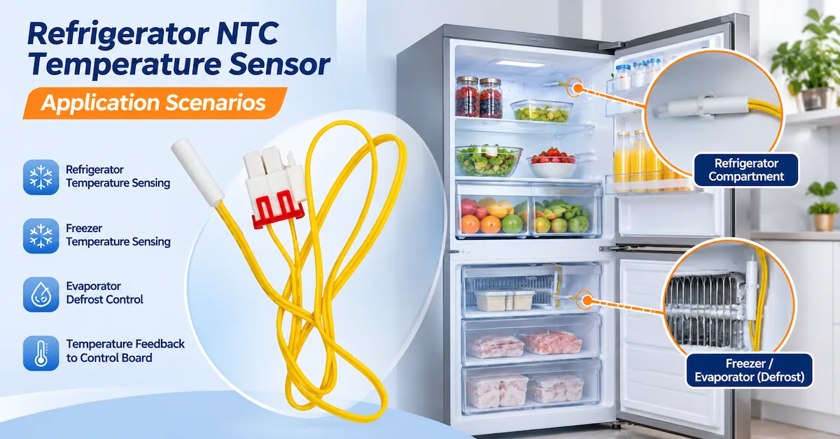
A refrigeration controller does not directly measure temperature using a conventional NTC thermistor.
Instead, it measures an electrical quantity related to resistance and converts that measurement into a temperature value using an expected resistance–temperature characteristic.
If the actual sensor curve differs from the controller's calibration, the interpreted temperature can be incorrect.
R25 does not define the entire sensor curve
R25 is the thermistor's nominal resistance at 25°C under specified measurement conditions.
Two sensors may both have a nominal R25 of 10kΩ.
However, their resistance at 0°C or -18°C may differ because their material characteristics and B values are different.
This becomes particularly important for freezer and evaporator sensing, where the operating temperature may be far below the room-temperature reference point.
What does the B value mean?
The B value describes the thermistor's resistance–temperature relationship over a specified reference temperature interval.
For example:
-
B25/50 refers to a relationship defined between 25°C and 50°C.
-
B0/50 refers to a relationship defined between 0°C and 50°C.
-
B25/85 refers to a relationship defined between 25°C and 85°C.
These specifications should not be treated as automatically interchangeable.
The exact reference temperatures matter.
Why the reference-temperature notation must be checked
For a practical example, Tianrui's DA32-00006W Refrigerator Defrost Temperature Sensor lists R0 = 13.251kΩ ±2% and B0/50 = 3218 ±1%. Engineers should verify these reference conditions against the original control-board specification before approving a replacement.
A refrigerator sensor specification may use R0 rather than R25.
For OEM refrigerator applications, engineers should review the exact specifications of NTC Temperature Sensor Assemblies, including reference resistance, B-value notation, probe construction, and connector requirements.
R0 refers to the nominal resistance at 0°C.
For example, a refrigerator-probe listing on Tianrui's website identifies:
| Parameter | Published Listing |
|---|---|
| Reference resistance | R0 = 13.251kΩ ±2% |
| B-value reference | B0/50 = 3218K ±1% |
| Probe housing | Ø7 × 25mm ABS |
| Coating | Epoxy |
| Lead wire | UL2651 AWG26 |
| Connector | 35965-0200 |
These values appear in the site's refrigerator defrost sensor product information.
They should not be rewritten as R25 = 13.251kΩ or B25/50 = 3218K.
Because reference-temperature notation differs between some published descriptions, the controlled manufacturer specification should be confirmed before establishing acceptance limits.
Why can the controller display the wrong temperature?
Possible causes include:
-
Incorrect R25 or R0 specification.
-
Different B value or full R–T curve.
-
Sensor resistance tolerance.
-
Wiring or connector faults.
-
Incorrect control-board reference resistance.
-
ADC or voltage-reference errors.
-
Firmware lookup-table mismatch.
-
Sensor installation and thermal-contact differences.
Engineering conclusion:
A matching resistance reading at one temperature does not prove that two refrigerator NTC sensors are interchangeable.
How to Build a Refrigerator NTC Resistance–Temperature Table
A useful R–T table identifies the expected sensor resistance at several reference temperatures.
It provides a consistent basis for engineering tests, incoming inspection, and replacement verification.
The preferred source is the manufacturer-issued resistance–temperature table for the exact model.
When only a nominal resistance and B value are available, a simplified B-parameter equation can support preliminary analysis.
Step 1: Obtain the correct reference values
The engineer should first confirm:
-
Full sensor part number.
-
Nominal resistance and reference temperature.
-
Resistance tolerance.
-
B value and its reference interval.
-
Approved operating temperature range.
-
Available manufacturer R–T data.
When evaluating replacement sensing elements, OEM engineers can review NTC Thermistor Components and request the model-specific R–T data needed to establish accurate resistance acceptance limits.
A value labeled R0 must not be substituted for R25.
Step 2: Apply the simplified B-parameter equation
A commonly used approximation is:
R(T) = Rref × exp[B × (1/T − 1/Tref)]
Where:
-
R(T) = estimated resistance at temperature T.
-
Rref = nominal resistance at the reference temperature.
-
B = specified B parameter in kelvin.
-
T = target temperature in kelvin.
-
Tref = reference temperature in kelvin.
Convert Celsius temperatures to kelvin:
T(K) = T(°C) + 273.15
This simplified equation assumes a constant B value.
Actual NTC materials may not follow a single constant-B relationship precisely across a wide temperature range.
For final qualification, particularly below the B-value reference interval, use the manufacturer's complete R–T table or an approved calibration model.
Step 3: Calculate an illustrative three-point worksheet
Illustrative Engineering Example — Not Tianrui Factory Test Data
Assume two hypothetical NTC sensors:
| Parameter | Example Sensor A | Example Sensor B |
|---|---|---|
| Nominal R25 | 10kΩ | 10kΩ |
| B parameter | 3950K | 3435K |
| R25 tolerance | Not specified in example | Not specified in example |
| Calculation model | Constant-B approximation | Constant-B approximation |
Both sensors have the same nominal resistance at 25°C.
However, the calculated values differ at lower temperatures.
Table 1. Illustrative NTC R–T Resistance Comparison
| Test Temperature | Sensor A: 10kΩ / B3950 | Sensor B: 10kΩ / B3435 | Engineering Interpretation |
|---|---|---|---|
| -18°C | 93.25kΩ | 69.70kΩ | Large difference at freezer temperature |
| 0°C | 33.62kΩ | 28.70kΩ | Different resistance despite equal R25 |
| 25°C | 10.00kΩ | 10.00kΩ | Both match at the reference temperature |
These values are theoretical calculations only.
They do not establish the actual tolerances or low-temperature behavior of any Tianrui refrigerator sensor.
They also extrapolate the constant-B model outside the typical 25–50°C reference interval, so they must not be used as production pass/fail limits.
Why this comparison matters
A technician measuring only the room-temperature resistance might conclude that both sensors are suitable replacements.
However, their low-temperature resistance characteristics differ substantially.
If the refrigerator controller expects Sensor A, installing Sensor B could cause the controller to interpret the actual freezer temperature incorrectly.
The result may affect:
-
Compressor cycling.
-
Freezer temperature regulation.
-
Evaporator temperature interpretation.
-
Defrost termination decisions.
-
Temperature alarms.
The exact outcome depends on the controller's circuit and software.
Step 4: Create a usable R–T inspection worksheet
Table 2. Refrigerator NTC Three-Point Test Worksheet
| Test Point | Reference Temperature | Approved Resistance Range | Measured Resistance | Deviation | Pass/Fail |
|---|---|---|---|---|---|
| T1 | -18°C | From controlled datasheet | ______ kΩ | ______ % | ______ |
| T2 | 0°C | From controlled datasheet | ______ kΩ | ______ % | ______ |
| T3 | 25°C | From controlled datasheet | ______ kΩ | ______ % | ______ |
Deviation (%) = (Measured Resistance − Nominal Reference Resistance) / Nominal Reference Resistance × 100
The acceptance limits should be derived from the exact sensor specification.
Do not apply a universal resistance tolerance to all NTC models.
Step 5: Consider total measurement uncertainty
The measured resistance may be affected by:
-
Reference temperature accuracy.
-
Temperature stability.
-
Multimeter accuracy.
-
Sensor self-heating.
-
Measurement lead resistance.
-
Thermal equilibrium.
-
Probe installation.
-
Manufacturer resistance and B-value tolerances.
A professional test worksheet should identify the measurement method and uncertainty appropriate to the project.
How to Test an NTC Sensor at -18°C, 0°C and 25°C
A three-point test can provide more useful information than a single measurement at room temperature.
The test should use controlled temperature conditions and a properly isolated sensor.
Electrical safety:
Disconnect the appliance from its power source and follow the manufacturer's servicing procedures before unplugging a probe or measuring resistance. Do not use an ohmmeter on an energized control circuit.
Step 1: Identify the sensor and test conditions
Record:
-
Sensor manufacturer.
-
Full part number.
-
Probe construction.
-
Approved temperature range.
-
Resistance specification.
-
B value.
-
Test equipment identification.
Confirm that the target temperatures are within the sensor assembly's rated operating range.
Step 2: Verify the test instruments
Use an appropriately calibrated or verified temperature reference and resistance-measurement instrument.
The measurement current should be low enough to avoid significant thermistor self-heating.
If the manufacturer's datasheet defines a measurement procedure, follow it.
Step 3: Test at 25°C
Place the sensor in a temperature-controlled environment near 25°C.
Allow sufficient time for the sensing element to stabilize.
Measure the resistance.
Compare it with the approved R25 specification.
If a sensor uses another nominal reference temperature, such as R0, follow its corresponding specification.
Step 4: Test at 0°C
A properly prepared ice-water reference bath can provide a useful 0°C condition.
However, do not immerse a non-waterproof sensor or exposed electrical connection in water.
For assemblies not rated for immersion, use a suitable dry temperature-controlled fixture or protected reference arrangement.
Wait until the sensing element reaches thermal equilibrium.
Record the resistance.
Step 5: Test at -18°C
Use an appropriately controlled low-temperature chamber or another validated method capable of maintaining the required test condition.
A standard ice-water bath cannot establish -18°C.
Place the sensor in the controlled environment and allow it to stabilize.
Measure the resistance and compare the result with the manufacturer-approved value at -18°C.
Step 6: Compare the full measurement set
The three readings should be evaluated together.
A sample may pass the 25°C check but fail at -18°C.
This can indicate a resistance-curve mismatch, an out-of-tolerance component, or a measurement problem.
The engineer should investigate the cause rather than immediately classify the sensor as defective.
Step 7: Document the results
Table 3. OEM Multi-Temperature Measurement Record
| Measurement Item | -18°C | 0°C | 25°C |
|---|---|---|---|
| Reference instrument temperature | ______ | ______ | ______ |
| Temperature stability | ______ | ______ | ______ |
| Sensor resistance | ______ | ______ | ______ |
| Approved nominal resistance | ______ | ______ | ______ |
| Approved resistance tolerance | ______ | ______ | ______ |
| Resistance deviation | ______ | ______ | ______ |
| Pass/fail result | ______ | ______ | ______ |
| Technician / date | ______ | ______ | ______ |
This worksheet can be used during engineering validation and adapted for production inspection.
The OEM should define test temperatures and sampling requirements according to the application and approved sensor specification.
How to Identify Open Circuit, Short Circuit and Sensor Drift
Different faults can produce different electrical symptoms.
However, an abnormal refrigerator temperature reading does not necessarily mean the sensing element has failed.
The wiring harness, connector, and control-board input circuit must also be considered.
Table 4. Refrigerator NTC Fault Diagnosis Matrix
| Observed Condition | Possible Cause | Recommended Check |
|---|---|---|
| Near-infinite resistance | Open thermistor, broken lead, disconnected connector | Measure at probe and harness separately |
| Near-zero resistance | Shorted sensor or cable | Inspect wiring and isolated sensor |
| Resistance outside approved range | Wrong sensor curve, damaged element, temperature error | Verify at controlled temperatures |
| Correct resistance at 25°C, incorrect at -18°C | B-value mismatch or curve deviation | Compare complete R–T characteristic |
| Reading changes when cable moves | Intermittent conductor or connector | Conduct controlled continuity and flex tests |
| Sensor resistance correct, controller reading incorrect | Board input, ADC, firmware or calibration issue | Check the approved control-board diagnostic procedure |
| Slow temperature response | Poor thermal contact, large probe mass, encapsulation differences | Compare response under defined conditions |
| Intermittent behavior after condensation | Moisture ingress or connector contamination | Inspect and test under relevant environmental conditions |
Open-circuit behavior
A disconnected NTC probe often appears as very high resistance when measured independently.
However, the temperature or error value displayed by a control board depends on the circuit and firmware.
Some controllers interpret an open circuit as extremely low temperature; others may display an error code or use a fallback value.
There is no universal display behavior.
Short-circuit behavior
A shorted probe or cable can produce a very low resistance reading.
Again, the controller's interpretation depends on the electrical circuit.
For some voltage-divider arrangements, a short produces an ADC reading near one supply rail.
A different circuit arrangement can produce the opposite response.
Sensor drift
Sensor drift refers to changes in electrical characteristics over time.
Potential contributors include thermal aging, moisture exposure, material changes, and mechanical stress.
A drift investigation should compare measured values with the original approved R–T specification.
Why a resistance reading is not the whole diagnosis
An NTC sensor can have acceptable resistance while still being installed incorrectly.
Poor contact with the evaporator, excessive cable routing near heat sources, or unsuitable probe placement can create a mismatch between the sensor temperature and the temperature the controller needs to monitor.
Electrical accuracy and system thermal accuracy are separate requirements.
Sensor Failure or Control-Board Failure: How Can Engineers Tell?
A refrigerator temperature-control problem may originate from the thermistor, wiring harness, connector, analog input circuit, or firmware.
A structured diagnostic sequence can help isolate the fault.
Diagnostic Step 1: Confirm the reported problem
Record the appliance symptom:
-
Incorrect temperature display.
-
Unexpected compressor operation.
-
Repeated temperature alarms.
-
Abnormal defrost behavior.
-
Intermittent temperature readings.
Document the operating conditions.
Diagnostic Step 2: Isolate and measure the sensor
With the equipment safely disconnected, measure the thermistor resistance independently of the control board.
Compare the measurement with the approved R–T data at the actual sensor temperature.
If the sensor fails the approved resistance test, investigate the probe and its electrical connections.
Diagnostic Step 3: Check the harness
If the probe measures correctly, inspect its harness.
Check connector seating, cable continuity, terminal condition, and relevant insulation.
Where appropriate, compare resistance at the probe terminals with the resistance measured through the complete harness.
Diagnostic Step 4: Evaluate the control-board input
If the sensor and harness appear correct, a trained engineer can evaluate the control board according to the equipment manufacturer's approved procedures.
This may involve checking reference components, input voltage, ADC conversion, or diagnostic information.
Do not inject arbitrary voltages or bypass safety functions.
Where the manufacturer permits a known reference resistor to be used for diagnostics, follow the specified value and procedure.
Diagnostic Step 5: Check firmware interpretation
Even a correctly functioning analog input may produce incorrect temperature values if the firmware uses the wrong resistance table or calibration.
This is particularly relevant when replacing a sensor with a different B value.
Simplified diagnostic decision path
Temperature reading abnormal
↓
Isolate appliance and measure probe resistance at a known temperature
-
Outside approved range → investigate probe and measurement conditions.
-
Within approved range → continue to harness testing.
↓
Check harness and connector continuity
-
Abnormal → investigate wiring or connector.
-
Normal → continue to approved board diagnostics.
↓
Check control-board input and temperature conversion
-
Electrical input abnormal → investigate board circuitry.
-
Electrical input normal, temperature interpretation abnormal → investigate calibration, firmware, and sensor configuration.
↓
Validate the corrected system at multiple temperatures
This process should not be used to declare a board defective without the relevant controller-specific diagnostic evidence.
How does a control-board voltage divider affect the reading?
Many NTC measurement circuits use a resistor divider connected to an analog-to-digital converter.
For an illustrative circuit with:
-
A fixed 10kΩ pull-up resistor.
-
A thermistor connected between the ADC input and ground.
-
A 3.3V reference.
The nominal divider relationship is:
VADC = 3.3 × RNTC / (10kΩ + RNTC)
At 25°C, a 10kΩ thermistor would produce approximately 1.65V in this idealized circuit.
At lower temperatures, its resistance increases, so the ADC voltage rises in this particular arrangement.
A controller designed for a different R–T curve may translate that voltage into the wrong temperature.
This is an illustrative circuit only. Actual refrigerator controllers may use different resistor values, sensor polarity, ADC references, or measurement architectures.
The appropriate reference circuit must come from the appliance design.
How to Verify a Freezer Temperature Sensor Replacement
A replacement freezer temperature sensor should satisfy the same relevant electrical, thermal, and mechanical requirements as the approved original component.
The fact that two probes have similar housings or connectors does not establish compatibility.
Table 5. OEM Freezer Sensor Replacement Compatibility Matrix
| Comparison Item | Original Sensor | Replacement Candidate | Approval Requirement |
|---|---|---|---|
| Full part number | ______ | ______ | Confirm exact identification |
| Nominal resistance | ______ | ______ | Match approved reference |
| Reference temperature | R0 / R25 / other | R0 / R25 / other | Use consistent reference |
| B value | ______ | ______ | Confirm value and reference interval |
| R–T table at -18°C | ______ | ______ | Within approved limits |
| R–T table at 0°C | ______ | ______ | Within approved limits |
| R–T table at 25°C | ______ | ______ | Within approved limits |
| Operating temperature range | ______ | ______ | Cover complete application |
| Probe dimensions | ______ | ______ | Fit installation |
| Housing material | ______ | ______ | Environmental suitability |
| Cable length | ______ | ______ | Routing and resistance requirements |
| Connector | ______ | ______ | Mechanical and electrical match |
| Pin assignment | ______ | ______ | Confirm wiring configuration |
| Thermal response | ______ | ______ | Meet control-system requirements |
| Sealing and insulation | ______ | ______ | Meet application requirements |
| Controller compatibility | ______ | ______ | Validate temperature conversion |
| Final status | Approved | Pending | Engineering approval |
Why matching 10kΩ is insufficient
A freezer controller expects a resistance corresponding to its programmed temperature relationship.
A replacement with the same R25 but different B value may produce acceptable readings at room temperature and incorrect readings at low temperatures.
This is why the three-point R–T worksheet is an important early verification tool.
Why connector compatibility matters
A replacement probe may have correct thermal characteristics but an unsuitable connector.
Potential problems include:
-
Incorrect housing dimensions.
-
Different terminal arrangement.
-
Unapproved wire length.
-
Different locking features.
-
Inadequate sealing.
-
Insufficient cable temperature rating.
OEM buyers should request dimensional drawings and connector specifications rather than relying on product photographs.
For replacement projects requiring different probe housings, cable lengths, or connectors, Tianrui's NTC Temperature Sensor Assemblies provide a starting point for discussing application-specific OEM requirements.
How should controller compatibility be approved?
The engineering team should verify the replacement in the actual controller.
Testing should cover the required measurement range and applicable defrost-control conditions.
If firmware changes are required to support the replacement's R–T curve, the component is not a simple drop-in replacement.
Such changes should be managed through the appliance's engineering change-control process.
Tianrui offers NTC Temperature Sensor assemblies, including products with configurable probe structures, cables, and connectors.
What Environmental Tests Matter for Refrigerator NTC Probes?
Refrigerator sensors operate in environments where temperature changes and moisture exposure can affect performance.
A freezer probe may encounter condensation, ice, repeated thermal cycling, and mechanical stress from installation or service.
The complete sensor assembly should be considered.
Temperature cycling
Repeated temperature changes can stress the sensing element, encapsulation, housing, and cable.
The OEM should evaluate electrical characteristics before and after the specified cycling test.
Condensation and moisture exposure
Moisture can enter improperly sealed sensor structures and affect resistance stability or insulation.
Where the installation involves direct liquid exposure, the sensor must be qualified for that environment.
A generic statement that a probe is waterproof is not sufficient without relevant construction and testing information.
Cable bending
Wires may be bent during assembly or appliance maintenance.
Excessive strain can damage the conductor, insulation, or connection to the sensor element.
The OEM should define relevant flexing and strain-relief requirements.
Connector durability
Connectors may experience repeated temperature changes, vibration, and moisture.
Inspection should address terminal condition, retention, electrical continuity, and any relevant environmental requirements.
Thermal response
The probe housing and encapsulation affect the speed with which the sensing element follows temperature changes.
For an evaporator or defrost application, response characteristics may be important to the controller's operation.
A replacement with the same electrical curve but substantially different thermal response may still require system validation.
Table 6. Refrigerator NTC Environmental Qualification Plan
| Test | Main Concern | Recommended Evaluation |
|---|---|---|
| Low-temperature operation | Electrical performance at freezer temperatures | R–T measurement |
| Temperature cycling | Material and connection fatigue | Before-and-after electrical checks |
| Condensation exposure | Moisture ingress | Insulation and resistance stability |
| Cable flexing | Conductor damage | Continuity and mechanical integrity |
| Connector retention | Intermittent contacts | Electrical and mechanical checks |
| Thermal response | Temperature measurement delay | Defined response-time test |
| Extended temperature exposure | Drift | Resistance and calibration comparison |
| Mounting verification | Thermal contact and placement | Installed system response |
Acceptance criteria and test conditions should be defined for the exact product.
OEM Acceptance Tests for Refrigerator NTC Sensor Assemblies
OEM refrigerator manufacturers need a repeatable method for qualifying incoming sensor assemblies.
The inspection plan should cover both the thermistor's electrical characteristics and the completed probe construction.
Table 7. Incoming Quality Control Checklist
| Inspection Item | Required Evidence | Recommended Record |
|---|---|---|
| Part number | Approved drawing/BOM | Model and revision |
| R25 or R0 | Approved datasheet | Measured reference resistance |
| R–T performance | Manufacturer reference table | Multi-temperature readings |
| B-value compatibility | Defined B characteristic | Verification result |
| Probe size | Mechanical drawing | Dimensional inspection |
| Cable length | Approved drawing | Measured length |
| Connector | Approved connector specification | Visual and fit check |
| Wire continuity | Electrical test | Pass/fail result |
| Insulation | Relevant assembly requirement | Test result |
| Environmental durability | Project qualification plan | Qualification report |
| Traceability | Supplier and production records | Lot or batch identification |
What should be tested on every production lot?
The specific incoming inspection plan depends on product risk, process capability, and contractual requirements.
Routine inspection may differ from full engineering qualification.
For example, a manufacturer may use a defined resistance test for routine acceptance while conducting more extensive multi-temperature and environmental tests during qualification or periodic verification.
However, the sampling frequency and acceptance limits must be established through an approved quality plan.
They should not be invented.
Relevant NTC component standard
The official IEC 60539-1:2022 — Directly Heated Negative Temperature Coefficient Thermistors establishes terminology, inspection procedures, and relevant testing methods for directly heated NTC thermistors.
This standard can support component-level qualification planning.
It does not prescribe a universal refrigerator probe resistance table.
The OEM must still define the approved NTC curve and completed-assembly requirements.
Refrigeration appliance safety
For household and similar refrigerating appliances, IEC 60335-2-24:2025 addresses particular safety requirements within its defined scope.
The complete appliance's relevant electrical and control-system functions must be evaluated as applicable.
A temperature sensor passing an R–T test does not, by itself, establish appliance safety or certification.
How can Tianrui support a custom replacement project?
Dongguan Tianrui Electronics Co., Ltd. publishes NTC sensing products for appliance and electronic applications.
OEM manufacturers can explore Tianrui's NTC Temperature Sensor Products when evaluating customized resistance characteristics, probe dimensions, cable assemblies, and connector configurations.
Its catalog includes epoxy-coated probes, plastic and metal housings, and other temperature-sensor constructions.
For OEM replacement projects, the most useful starting point is an approved original sensor specification and a sample.
The manufacturer can then evaluate the requested resistance characteristic, housing, cable, connector, and other project requirements.
Specific feasibility, model availability, test documentation, sample quantity, MOQ, and production lead time should be confirmed during the technical review.
OEM Refrigerator NTC Sensor RFQ Checklist
Provide the following information:
| RFQ Field | Required Information |
|---|---|
| Application | Refrigerator, freezer, evaporator, or defrost control |
| Original part number | Complete model identifier |
| Original datasheet | R–T data and tolerances |
| R25 or R0 | Nominal resistance and reference temperature |
| B value | Value and reference interval |
| Operating temperature | Required minimum and maximum |
| Control-board information | Approved sensor curve and interface |
| Probe dimensions | Drawing or original sample |
| Housing | Material, size, and protection requirement |
| Cable | Length, insulation, and routing requirements |
| Connector | Part number and terminal arrangement |
| Environmental exposure | Condensation, freezing, vibration, cleaning |
| Test requirements | R–T, insulation, durability, and system tests |
| Samples | Engineering evaluation quantity |
| Production forecast | Initial and annual purchasing volume |
Example OEM Technical Inquiry
Subject: Refrigerator NTC Temperature Sensor — R–T Curve Matching and OEM Replacement
We are evaluating an NTC temperature sensor for a refrigerator/freezer control system.
Our project requires compatibility with an existing temperature-control board.
We need to verify the sensor's resistance at -18°C, 0°C, and 25°C, along with its R25 or R0 specification, B value, mechanical construction, and wiring.
We can provide the original sensor sample, connector information, application drawings, and projected annual purchasing quantity.
Please advise:
-
Which Tianrui NTC temperature-sensor models may be suitable.
-
Whether the required R–T characteristic can be matched.
-
What resistance tolerances apply at the relevant temperatures.
-
Whether probe dimensions, cable length, and connector can be customized.
-
What samples and technical documents are available.
-
What testing is recommended before replacement approval.
-
What project-specific MOQ and lead-time conditions apply.
We would like to complete engineering verification before approving the production component.
For a technical evaluation, contact Tianrui Electronics with your original sensor specifications and application requirements.
Frequently Asked Questions About Refrigerator NTC Sensor Testing
1. Does every refrigerator NTC temperature sensor use 10kΩ resistance?
No.
Refrigerator NTC sensors can use different nominal resistance values and reference temperatures.
The correct specification depends on the control board's expected resistance–temperature characteristic.
A 10kΩ sensor is not automatically compatible with every refrigerator controller.
2. Why is NTC resistance higher at -18°C than at 25°C?
An NTC thermistor generally increases in resistance as temperature decreases.
This is why a sensor may measure a significantly higher resistance inside a freezer than at room temperature.
The exact value depends on the thermistor's resistance–temperature characteristic.
3. How do I calculate NTC resistance at -18°C?
Use the manufacturer-approved R–T table whenever available.
For preliminary calculations, a simplified B-parameter equation can estimate resistance using a specified reference resistance and B value.
However, extrapolation outside the B-value reference interval may introduce error.
The calculated value should not replace the manufacturer's acceptance specification.
4. Can a 10kΩ B3435 sensor replace a 10kΩ B3950 sensor?
Not automatically.
Although both have a nominal resistance of 10kΩ at 25°C, their resistance values differ at other temperatures.
The replacement must match the controller's required temperature curve within the approved tolerance range.
Multi-temperature and installed-system testing are required.
5. How do you test a freezer temperature sensor with a multimeter?
Disconnect the appliance safely and isolate the sensor from the control circuit.
Measure resistance at a known, stabilized temperature using an appropriate instrument.
Compare the result with the approved sensor specification.
For a more complete assessment, repeat the measurement at multiple temperatures.
6. What does an open-circuit NTC sensor look like electrically?
An open sensor or disconnected lead often measures extremely high or infinite resistance when tested independently.
However, the controller's displayed temperature or error code depends on the board design and software.
An open-circuit indication should also prompt inspection of the harness and connector.
7. Why does a refrigerator sensor pass at 25°C but fail at freezer temperature?
The sensor may have an incorrect B value, a different resistance–temperature characteristic, or temperature-dependent damage.
Measurement errors and insufficient thermal stabilization are also possible.
A three-point test helps identify these differences.
8. Can a freezer temperature sensor replace a refrigerator compartment sensor?
Possibly, but only if its electrical characteristics, environmental rating, mechanical design, and controller compatibility meet the relevant requirements.
The fact that both sensors operate in refrigeration equipment does not establish interchangeability.
9. How can engineers distinguish a sensor fault from a control-board fault?
First verify the sensor independently at known temperatures.
Next inspect the harness and connectors.
If these components meet their specifications, evaluate the board input and firmware using approved diagnostic procedures.
A correct sensor resistance alone does not prove the control board is defective.
10. What information is required for a custom refrigerator NTC probe quotation?
Provide the original part number, R–T specification, R25 or R0, B value, required temperature range, housing dimensions, cable and connector details, environmental requirements, and estimated purchasing quantity.
An original sample and control-board information can help clarify replacement compatibility.
Conclusion
Verifying a refrigerator NTC temperature sensor requires more than checking whether its connector fits or whether its room-temperature resistance looks correct.
The most important requirement is ensuring that the sensor's electrical behavior matches the temperature conversion expected by the refrigerator's control board.
For refrigerator OEMs, refrigeration engineers, and component purchasing teams, the recommended verification process is:
-
Confirm the exact specification: Identify R25 or R0, B value, reference-temperature interval, and approved tolerances.
-
Build an R–T reference: Use the manufacturer's complete resistance–temperature table whenever possible.
-
Perform multi-temperature testing: Evaluate representative points such as -18°C, 0°C, and 25°C under controlled conditions.
-
Diagnose faults systematically: Separate the probe, harness, connector, control-board input, and firmware.
-
Verify replacement compatibility: Compare electrical, thermal, mechanical, and environmental requirements.
-
Establish OEM acceptance criteria: Use controlled drawings, test records, and approved inspection procedures.
-
Qualify the completed appliance: Confirm the replacement sensor works correctly within the actual refrigeration-control system.
An NTC sensor for refrigerator applications must be electrically compatible with the controller and mechanically suitable for its installation environment.
A freezer temperature sensor may require particular attention to low-temperature resistance behavior, condensation exposure, and defrost-related performance.
Dongguan Tianrui Electronics Co., Ltd. supplies NTC temperature-sensing components and probe assemblies for OEM appliance development.
Its product range includes different resistance configurations, sensor structures, cable arrangements, and connector options subject to application-specific review.
Need an NTC temperature sensor that matches an existing refrigerator control board?
Explore Tianrui's NTC Temperature Sensor Products or contact Tianrui Electronics to discuss R–T curve matching, engineering samples, probe customization, and OEM replacement verification.
Share your original sensor datasheet, -18°C/0°C/25°C resistance requirements, control-board information, probe dimensions, connector details, and estimated production volume.
Email:
Phone:
+86 135 3277 2961
A verified resistance–temperature characteristic, controlled fault-diagnosis procedure, and approved replacement qualification process provide the foundation for reliable refrigerator temperature sensing and long-term OEM component sourcing.