Quick Answer: What Are the Real Disadvantages of PTC Heating Elements?
The main PTC heating element disadvantages are potentially high startup current, heating power that varies with cooling conditions, limited temperature precision without feedback control, thermal-interface losses, restricted-airflow risks, ceramic brittleness, and production variation. These limitations do not affect every design equally. Engineers should identify the actual failure symptom, measure electrical and thermal behavior under defined conditions, and validate an appropriate component or system-level correction.
Key Takeaways
-
Cold-start current: Evaluate actual transient current rather than sizing the supply from steady-state wattage alone.
-
Thermal-load sensitivity: A self-regulating PTC heater may draw different power under different cooling conditions.
-
Control accuracy: PTC self-regulation does not guarantee precise temperature at the heated object.
-
Contact resistance: Poor thermal coupling can reduce useful heat transfer.
-
Restricted airflow: Reduced air movement can create unacceptable temperatures in the completed assembly.
-
Ceramic durability: Point loading, unsuitable mounting, and thermal cycling may damage brittle ceramic elements.
-
Production consistency: R–T behavior, dimensions, electrode connections, and insulation should be controlled across batches.
For OEM engineers, the most useful question is not whether PTC technology is generally good or bad.
It is:
Which measurable limitation is preventing the heating assembly from meeting its electrical, thermal, mechanical, or reliability requirements?
Dongguan Tianrui Electronics Co., Ltd. supplies ceramic PTC elements, aluminum-shell heaters, and insulated heating assemblies for OEM applications.
Its existing PTC Heating Element OEM Design Guide explains component selection and design fundamentals, while the Self-Regulating PTC Heater Thermal Balance Guide addresses thermal operating behavior.
This article takes a troubleshooting approach: seven failure scenarios, the tests needed to investigate them, and the engineering changes that may resolve them.
Are PTC Heater Disadvantages Caused by the Ceramic or the System?
A positive temperature coefficient heating element changes electrical resistance as its temperature changes.
In many ceramic PTC heaters, resistance rises sharply near a characteristic transition region, reducing electrical input under the relevant operating conditions.
However, the behavior of a complete heater depends on more than its ceramic material.
Three levels should be evaluated separately.
| Engineering Level | Relevant Variables | Typical Problem |
|---|---|---|
| Ceramic element | Resistance–temperature behavior, dimensions, electrodes, material characteristics | Unexpected current or switching behavior |
| Heater assembly | Housing, insulation, mounting pressure, thermal interface, wiring | Uneven heating or mechanical damage |
| Finished equipment | Supply, airflow, sensors, controls, enclosure, protective devices | Temperature errors or abnormal-condition risks |
A design problem may originate at one level but appear as a failure elsewhere.
For example, an enclosure may warm too slowly because the ceramic is unsuitable, the thermal interface is poor, or the intended thermal load exceeds the assembly's capabilities.
These causes require different corrective actions.
Engineering rule:
Identify the failure mechanism before changing the heater specification.
Disadvantage 1: High Cold-Start Current
When does this problem occur?
Startup-current problems can occur when a relatively cold PTC heating element is energized from a supply that cannot comfortably support its initial electrical demand.
This issue can be particularly important in battery-powered devices, compact power supplies, and systems with several heaters operating simultaneously.
The current profile depends on the PTC's resistance–temperature characteristic, initial temperature, applied voltage, and heating conditions.
The peak does not necessarily occur at the exact instant of energization.
Observable symptoms
-
Supply voltage drops during startup.
-
Power supply enters current limiting.
-
Protection devices operate unexpectedly.
-
Heater startup is inconsistent.
-
Relay contacts or switching devices experience excessive stress.
Possible causes
The initial electrical resistance may be lower than the resistance reached after heating.
Using stabilized power consumption to estimate the required startup current can therefore underestimate the electrical demand.
For an approximately resistive heating element:
I(t) = V(t) / R(T,t)
Resistance changes as the element heats, so current must be evaluated over time.
How should engineers test it?
Measure:
-
Initial ceramic and ambient temperature.
-
Applied supply voltage.
-
Current-versus-time waveform.
-
Peak measured current and its duration.
-
Supply-voltage response.
-
Switching-device behavior.
-
Current after thermal stabilization.
For model-specific electrical evaluation, engineers can review Tianrui's MZ41 Ceramic PTC Heating Element and request the applicable resistance-temperature characteristics and startup-current test data before finalizing the power supply design.
Repeat the test under relevant minimum and maximum starting-temperature conditions.
Use equipment with adequate measurement bandwidth and a suitably controlled test setup.
Engineering fixes
-
Match the supply and protection devices to the measured startup demand.
-
Evaluate a PTC element with a more suitable electrical characteristic.
-
Consider staged startup when multiple heaters share a supply.
-
Review conductor, connector, and switching-device ratings.
-
Evaluate controlled power application where appropriate.
Do not assume that adding a current limiter will have no effect on heating performance.
Validation target:
The heater must start reliably throughout the specified operating range without unacceptable electrical stress or unintended protective operation.
Disadvantage 2: Heating Power Changes with Cooling Conditions
When does this problem occur?
A self-regulating PTC heater operates at an equilibrium determined by electrical input and heat dissipation.
Changes in airflow, contact conditions, ambient temperature, or the heated object's thermal load can shift that equilibrium.
A component that performs adequately in one laboratory fixture may deliver different heating power in the finished product.
Observable symptoms
-
Electrical power varies between installation configurations.
-
Warm-up time changes under different thermal loads.
-
Output is inconsistent between open-air and enclosed operation.
-
A heater meets its nominal description but cannot satisfy the system's required heat-up time.
Possible causes
When cooling removes heat from the PTC element, its temperature and resistance can change.
In the relevant operating region, stronger cooling may keep resistance lower and allow greater electrical input.
Reduced cooling may produce higher ceramic temperatures and lower electrical power.
The relationship is nonlinear and must be measured.
Higher electrical power does not automatically mean that useful heat reaches the intended target.
How should engineers test it?
Compare the same heater under controlled conditions such as:
-
Low and high ambient temperatures.
-
Minimum and maximum permitted airflow.
-
Different approved thermal loads.
-
Installed versus laboratory-fixture conditions.
Record voltage, current, power, ceramic temperature, target temperature, and warm-up time.
Engineering fixes
-
Select an element characteristic suited to the actual thermal load.
-
Improve the assembly's heat-transfer path.
-
Evaluate the complete heater under representative installed conditions.
-
Adjust the heating-module structure where needed.
-
Add feedback control if a specific target temperature must be maintained.
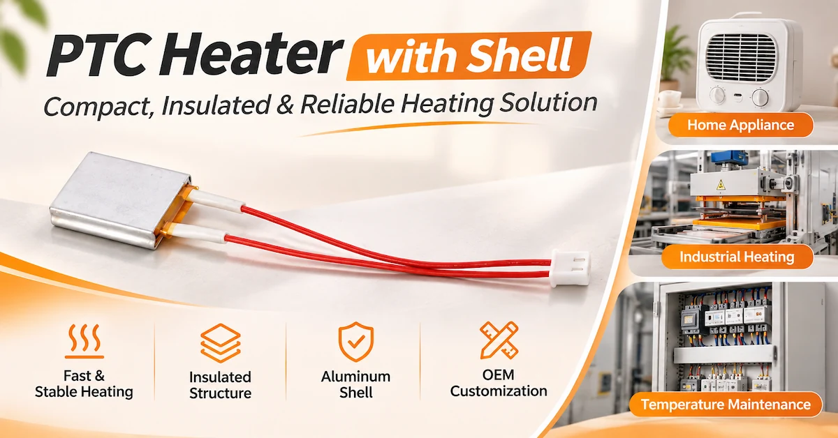
For applications requiring an insulated heating structure, Tianrui's PTC Heater with Insulating Film can be evaluated as an alternative assembly configuration. Its mechanical durability, thermal performance, and insulation characteristics should be verified under the intended operating conditions.
Practical example
An OEM may observe that a PTC heater consumes less electricity when its airflow is restricted.
That does not prove the product is performing better.
The reduced input may be associated with higher ceramic temperature and less useful heat reaching the intended air stream.
Validation target:
Useful heating performance must meet the equipment specification under every relevant normal operating condition.
Disadvantage 3: Self-Regulation Is Not Precise Temperature Control
When does this problem occur?
A PTC heater may be selected because its ceramic resistance rises at elevated temperature.
However, the temperature of the heated object can differ from the ceramic temperature.
This becomes important in appliances requiring tightly controlled surface temperatures, repeatable processing temperatures, or uniform heating.
Observable symptoms
-
Target temperature exceeds or falls below the required range.
-
Temperature varies with ambient conditions.
-
Multiple locations on the heated surface have different temperatures.
-
Warm-up and steady-state behavior differ from expectations.
Possible causes
PTC self-regulation responds to the ceramic's own electrical and thermal conditions.
It does not directly measure the temperature of a contact plate, liquid, enclosure, or airflow outlet.
The thermal path, sensor position, control strategy, and heat load determine the final system temperature.
How should engineers test it?
Measure temperatures simultaneously at:
-
Ceramic element.
-
Heater housing or contact plate.
-
Heated object.
-
Relevant ambient location.
-
Other critical points in the assembly.
Repeat under expected minimum and maximum thermal loads.
Compare the measurements with the equipment's temperature tolerance and uniformity requirements.
Engineering fixes
-
Add an appropriately located temperature sensor.
-
Implement suitable closed-loop control.
-
Review heater distribution and thermal spreading.
-
Reduce unnecessary thermal resistance.
-
Introduce protective temperature limits as required by the application.
Feedback control and independent protective functions should be treated as separate engineering considerations where necessary.
Validation target:
The controlled object, not only the ceramic, must satisfy the required temperature range and stability.
Disadvantage 4: Thermal Contact Resistance Limits Useful Heating
When does this problem occur?
A PTC ceramic element may reach its operating temperature while the object being heated remains too cold.
This can occur in contact-heating applications where the element transfers heat through insulation, metal carriers, adhesive layers, or mechanical interfaces.
Observable symptoms
-
High element temperature but slow target warm-up.
-
Uneven temperature distribution.
-
Significant temperature difference across the thermal interface.
-
Strong dependence on assembly pressure.
-
Variation between otherwise similar units.
Possible causes
The thermal interface may contain air gaps, uneven contact, unsuitable insulating materials, or excessive layer thickness.
An approximate steady-state relationship is:
ΔT ≈ Q × Rth
Where:
-
ΔT = temperature difference across the thermal path.
-
Q = heat-transfer rate.
-
Rth = thermal resistance.
For a given heat flow, increased thermal resistance produces a larger temperature difference.
The actual assembly is more complex because PTC electrical power also changes with temperature.
How should engineers test it?
Measure the temperatures on both sides of the relevant interface where physically practical.
Compare:
-
Baseline assembly.
-
Controlled alternative contact pressure.
-
Approved interface material.
-
Alternative heat-spreader configuration.
Record target warm-up time and stabilized temperature distribution.
Avoid changing electrical insulation or exceeding ceramic mounting limits during testing.
Engineering fixes
-
Improve mating-surface flatness.
-
Apply a validated and repeatable clamping method.
-
Evaluate an appropriate thermally conductive insulating layer.
-
Reduce avoidable interface gaps.
-
Consider an integrated aluminum-shell structure.
-
Review electrode and insulation placement.
Tianrui's Aluminum Shell PTC Heater illustrates a construction combining PTC ceramic, an insulation layer, and an aluminum housing.
The supplier should confirm the exact electrical and thermal requirements for the intended configuration.
Validation target:
Improve useful heating performance while maintaining electrical insulation and ceramic mechanical integrity.
Disadvantage 5: Restricted Airflow Can Create Hot Spots
When does this problem occur?
PTC air-heating assemblies can encounter reduced airflow because of blocked outlets, fan failure, unsuitable duct installation, or accumulated debris.
The ceramic may reduce its electrical input as temperature rises.
However, the surrounding assembly may still experience excessive temperatures.
Observable symptoms
-
Localized heating near wiring or mounting parts.
-
Higher enclosure temperatures.
-
Unexpected thermal protection activation.
-
Discolored or damaged adjacent components.
-
Uneven outlet-air temperature.
Possible causes
When air movement decreases, less heat may be transferred away through forced convection.
The element and nearby structures reach a different thermal equilibrium.
A self-regulating characteristic does not prove that every surrounding material remains within its permissible temperature.
How should engineers test it?
In an appropriately controlled laboratory, evaluate relevant conditions such as:
-
Fan non-start.
-
Fan stoppage during heating.
-
Restricted air inlet.
-
Blocked outlet.
-
Abnormal controller operation.
Measure element temperature, nearby wiring and connector temperatures, enclosure hotspots, and protective-device responses.
Tests must follow the applicable equipment safety requirements.
Engineering fixes
-
Establish suitable airflow or fan-status monitoring.
-
Coordinate heater operation with required fan conditions.
-
Review component placement and enclosure clearance.
-
Add appropriate temperature monitoring and protective devices.
-
Verify the complete assembly under abnormal conditions.
For equipment using powered fans, protective design should not rely solely on the ceramic's self-regulating characteristic.
Validation target:
The completed product must satisfy applicable thermal and electrical safety requirements during relevant abnormal operation.
Disadvantage 6: Ceramic Brittleness and Thermal Cycling Risks
When does this problem occur?
Rigid ceramic PTC elements can be vulnerable to mechanical stress.
Stress may arise during assembly, clamping, transport, thermal expansion, or repeated changes in operating temperature.
An element that passes an initial electrical test may still be unsuitable for the mechanical conditions of the final product.
Observable symptoms
-
Visible ceramic cracks or edge damage.
-
Unstable electrical contacts.
-
Changes in resistance after assembly.
-
Intermittent heating.
-
Damage after thermal cycling or vibration.
Possible causes
Potential causes include:
-
Excessive point loading.
-
Uneven mounting pressure.
-
Differential expansion between ceramic and metal parts.
-
Insufficient mechanical support.
-
Electrode or connection stress.
-
Incompatible assembly methods.
Rigid ceramic elements should not be treated as flexible heating films.
How should engineers test it?
Before and after relevant mechanical and environmental tests, inspect:
-
Ceramic surfaces and edges.
-
Electrode condition.
-
Electrical resistance.
-
Connection continuity.
-
Insulation condition.
-
Heater output under defined conditions.
Apply assembly-force, vibration, and temperature-change tests that reflect the actual product environment.
Engineering fixes
-
Distribute mechanical loads appropriately.
-
Avoid concentrated clamping forces.
-
Allow for differential thermal expansion.
-
Improve mechanical support.
-
Review electrode attachment and strain relief.
-
Consider an integrated housing for demanding installations.
An aluminum enclosure may offer mechanical protection, but the internal ceramic still needs appropriate mounting and qualification.
Validation target:
The element and its connections must retain the required electrical and mechanical characteristics after the specified duty and environmental tests.
Disadvantage 7: Material and Production Variation
When does this problem occur?
OEMs may identify differences between samples, manufacturing batches, or alternative suppliers.
These differences become significant when the finished product has narrow electrical or thermal operating limits.
Observable symptoms
-
Different startup-current profiles between samples.
-
Variations in heating time.
-
Inconsistent temperature distribution.
-
Changes in resistance or switching behavior.
-
Assembly fit issues.
-
Insulation-test failures.
Possible causes
Relevant variables can include ceramic composition, processing, electrode construction, component dimensions, thermal-interface assembly, and insulation.
These characteristics are controlled through the product design and manufacturing process.
Normal production variation does not automatically indicate a defect.
The question is whether the resulting characteristics remain within the approved specification.
How should engineers test it?
Request the controlled model datasheet and verify:
-
Zero-power resistance.
-
Resistance–temperature behavior.
-
Relevant transition temperature.
-
Electrical ratings.
-
Ceramic dimensions.
-
Electrode and terminal construction.
-
Insulation requirements.
-
Applicable batch identification.
Where required, compare samples from different production lots.
Engineering fixes
-
Define measurable acceptance limits.
-
Approve an exact model and drawing revision.
-
Establish incoming inspection criteria.
-
Control critical assembly operations.
-
Require appropriate lot traceability.
-
Requalify relevant changes to materials or construction.
For example, Tianrui's MZ41 Ceramic PTC Heating Element lists a 24V DC configuration with a nominal 25°C resistance of 30Ω ±20% and a Curie temperature of 120°C ±10°C.
These are published parameters for the identified configuration, not universal tolerances for every PTC heating element.
The OEM must still verify application-specific startup, heating, and durability behavior.
Validation target:
Approved production variation must not cause the finished equipment to violate its electrical, thermal, mechanical, or safety requirements.
Which Tests Should OEMs Use to Verify These Limitations?
A structured validation process helps determine whether the problem originates in the ceramic, heating assembly, or finished equipment.
Instead of testing every characteristic independently, engineers should connect the failure symptom to a hypothesis, a controlled test, and an acceptance criterion.
Table 1. Seven PTC Heating Element Disadvantages — Engineering Diagnosis Matrix
| Problem | Observable Symptom | What Engineers Should Measure | Potential Engineering Fix |
|---|---|---|---|
| 1. Cold-start current | Supply droop, unintended protection operation | Peak current, duration, supply response | Match supply, switching, and protective devices |
| 2. Power changes with cooling | Inconsistent power or warm-up | Voltage, current, power, thermal load | Match PTC characteristic to actual cooling conditions |
| 3. Limited temperature precision | Target-temperature error | Ceramic and target temperatures, stability | Add suitable sensing and feedback control |
| 4. Thermal contact resistance | Hot ceramic, cold target | Interface temperature difference, warm-up | Improve contact, insulation, and heat spreading |
| 5. Restricted airflow | Hotspots, thermal-limit activation | Fan condition, local temperatures, protection response | Validate airflow monitoring and protective shutdown |
| 6. Ceramic brittleness | Cracks, resistance change, intermittent contact | Mechanical condition, continuity, post-cycle performance | Improve mounting and thermal-expansion accommodation |
| 7. Production variation | Unit-to-unit performance differences | R–T characteristics, dimensions, insulation, batch results | Establish controlled model specifications and QC |
This matrix is intended for engineering investigation, not as evidence that any particular Tianrui product has experienced all seven problems.
Table 2. OEM Problem Verification and Test Record
| Test ID | Test Condition | Measurement Required | Acceptance Criteria | Result |
|---|---|---|---|---|
| PTC-01 | Defined cold-start condition | Current waveform and supply response | OEM electrical specification | Pass / Fail |
| PTC-02 | Minimum and maximum thermal loads | Power, temperatures, warm-up time | OEM performance requirement | Pass / Fail |
| PTC-03 | Target-temperature regulation | Stability and temperature error | Approved control tolerance | Pass / Fail |
| PTC-04 | Thermal-interface comparison | Interface temperatures and useful heat transfer | Approved thermal performance | Pass / Fail |
| PTC-05 | Relevant airflow fault | Hotspots and protective response | Applicable equipment requirements | Pass / Fail |
| PTC-06 | Mechanical and temperature cycling | Damage, resistance, continuity | Approved durability limits | Pass / Fail |
| PTC-07 | Production sample comparison | R–T, dimensions, insulation | Controlled drawing and datasheet | Pass / Fail |
How to use this worksheet
Before testing, record the exact heater model, supply conditions, installation, ambient conditions, measuring equipment, and applicable acceptance limits.
Do not decide whether a sample passes only after seeing its results.
For each failure investigation, preserve the original configuration as a baseline and evaluate the proposed change under comparable conditions.
A useful investigation record should identify:
-
Original symptom.
-
Suspected failure mechanism.
-
Baseline measurement.
-
Proposed correction.
-
Modified sample identification.
-
Verification test.
-
Final engineering decision.
Which standards can support validation?
Three authoritative IEC publications provide relevant technical references.
IEC 60738-1:2022 — Directly Heated Positive Temperature Coefficient Thermistors
This standard establishes terminology, inspection procedures, and methods of test for PTC thermistors within its scope.
It provides a reference for documenting relevant component-level electrical characteristics.
IEC 60068-2-14:2023 — Environmental Testing: Change of Temperature
This standard addresses tests involving specified changes in ambient temperature.
It is relevant when evaluating the effects of temperature changes on components and assemblies.
The actual test severity and acceptance limits must be selected for the intended product.
IEC 60335-1:2020 — Household and Similar Electrical Appliances: General Safety Requirements
For household and similar equipment within its scope, this standard provides relevant appliance-level safety requirements.
The finished equipment may also require an applicable product-specific standard.
Referencing these publications does not establish that Tianrui or any particular PTC product has obtained certification.
Component testing and finished-equipment compliance remain distinct requirements.
When Should Engineers Choose a Different Heating Technology?
PTC heating elements can be effective where their electrical and thermal characteristics match the application.
However, they should not be selected automatically for every heating task.
A different heater architecture may be more suitable when a specific requirement conflicts with the behavior of the PTC system.
Table 3. When to Reconsider PTC Heating Technology
| OEM Requirement | Potential PTC Limitation | Alternative Design Direction |
|---|---|---|
| Very tight target-temperature tolerance | Self-regulation does not directly control target temperature | Closed-loop heating system with an appropriate sensor |
| Highly predictable fixed electrical power | Input power changes with thermal conditions | Controlled resistance heater or regulated power stage |
| Strict power-supply startup limit | Startup demand may exceed available current | Different PTC characteristic, power sequencing, or alternative heater |
| Limited thermal contact area | Interface losses may dominate performance | Different heater geometry or integrated contact structure |
| Severe mechanical bending | Rigid ceramic may crack | Qualified flexible heating technology |
| Complex airflow-fault requirements | Full system protection may be needed | Alternative heating architecture or redesigned protective system |
| Very narrow component-to-component tolerance | Standard PTC variation may be too broad | Tighter controlled specification or another heater design |
Is a traditional resistance heater always better?
No.
A conventional resistance heater has its own design and protection requirements.
It may offer a more predictable resistance characteristic over a defined temperature range, but this does not remove the need for temperature control, electrical protection, or thermal safety testing.
The preferred technology should be selected by comparing complete-system performance.
What if the problem can be corrected without replacing PTC?
In many projects, changing the ceramic material is not the first or best solution.
Improving the thermal interface, control system, mounting structure, electrical supply, or protective architecture may resolve the problem while preserving the original component concept.
The most economical approach depends on the required redesign, validation work, production volume, and total integration cost.
Which Tianrui products are relevant to different engineering problems?
| Product | Potential Engineering Use | Technical Consideration |
|---|---|---|
| MZ41 Ceramic PTC Heating Element | Ceramic-element evaluation and customization | Verify the exact electrical characteristic and mounting conditions |
| PTC Thermostatic Heating Elements | Comparing ceramic configurations and operating characteristics | Confirm the selected model rather than treating series ranges as one specification |
| Aluminum Shell PTC Heater | Reviewing integrated conductive-heating structures | Evaluate thermal interface and electrical insulation |
| PTC Heater with Insulating Film | Reviewing an insulated heater assembly | Verify the actual insulation construction and model-specific limits |
These links provide starting points for engineering inquiries.
They do not establish that a particular product will resolve a diagnosed failure without qualification.
What should OEM buyers include in a troubleshooting RFQ?
For effective technical review, share:
| Information | Why It Matters |
|---|---|
| Original heater model | Identifies the current configuration |
| Equipment application | Establishes the heating objective |
| Supply voltage and limits | Supports electrical compatibility |
| Startup-current measurements | Helps diagnose supply or switching problems |
| Thermal-load conditions | Explains power and temperature variation |
| Ceramic and target temperatures | Supports thermal-balance analysis |
| Assembly drawing | Identifies mechanical and interface limitations |
| Fault-test results | Documents abnormal operation |
| Existing protective devices | Supports safety review |
| Target performance | Defines measurable improvement |
| Sample and production quantity | Supports development and purchasing discussions |
For custom ceramic heaters, aluminum-shell assemblies, or insulated heating structures, contact Tianrui Electronics with the current product information and documented issue.
A measurement-based inquiry allows the supplier to evaluate whether the problem may require a different ceramic characteristic, assembly modification, or system-level design change.
Frequently Asked Questions About PTC Heating Element Disadvantages
1. What is the biggest disadvantage of a PTC heating element?
There is no single disadvantage that dominates every application.
For power-limited equipment, startup current may be critical.
For precision heating, target-temperature accuracy may be more important.
For forced-air systems, inadequate airflow and abnormal-condition protection may dominate the design review.
2. Do PTC heating elements always have high starting current?
No.
Startup behavior depends on the exact ceramic characteristic, initial temperature, operating voltage, and thermal conditions.
Engineers should use model-specific current measurements instead of assuming a universal startup multiplier.
3. Why does a PTC heater draw different power under different conditions?
Electrical resistance changes with ceramic temperature.
Cooling conditions affect that temperature, so electrical power can also change.
The actual relationship depends on the heater's R–T characteristic and the thermal system.
4. Can a self-regulating PTC heater maintain an exact temperature?
Not by self-regulation alone.
The ceramic's temperature-dependent resistance does not directly control the temperature of every heated object.
Applications requiring defined accuracy or uniformity may need external sensing and feedback control.
5. Why is a PTC heating element hot but the heated object remains cold?
Possible causes include excessive thermal-contact resistance, poor mounting, unsuitable heat spreading, or insufficient heating capability.
Compare ceramic, interface, and target temperatures before changing the component.
6. Can a PTC heater overheat if airflow is blocked?
A PTC ceramic may reduce its electrical input as its temperature rises.
However, the finished heating assembly can still develop unacceptable temperatures in surrounding materials.
Relevant blocked-airflow and fan-failure tests remain necessary.
7. Are ceramic PTC heating elements fragile?
Rigid ceramics can be damaged by excessive mechanical stress, point loading, or unsuitable assembly methods.
Proper mechanical support and application-specific durability testing are important.
8. Why do two PTC heating elements behave differently?
They may have different R–T characteristics, dimensions, electrode construction, or assembly conditions.
Variation can also occur within manufacturing tolerances.
An OEM should compare the exact approved specifications and test conditions.
9. Can an aluminum-shell PTC heater improve heat transfer?
An appropriately designed aluminum-shell assembly may improve heat spreading and mechanical integration.
However, the result depends on the ceramic, insulation, housing, contact surfaces, and actual thermal load.
The complete assembly should be tested.
10. What information should an OEM provide when a PTC heater fails qualification?
Provide the complete heater model, electrical supply, installation drawing, observed symptom, current and temperature measurements, relevant fault-test results, and required acceptance criteria.
This information helps identify whether the correction belongs at the ceramic, assembly, or equipment level.
Conclusion
Understanding PTC heating element disadvantages requires a practical engineering approach rather than a generic comparison of heating technologies.
The seven issues discussed in this guide—cold-start current, thermal-load-dependent power, temperature-control limitations, thermal-contact resistance, restricted airflow, ceramic mechanical stress, and production variation—describe potential challenges that should be evaluated against actual operating requirements.
They are not proof that every PTC heating element is unstable, inefficient, or unsafe.
For OEM engineers, the most effective troubleshooting process is to:
-
Identify the observable failure.
-
Determine whether the likely cause lies in the ceramic, assembly, or complete equipment.
-
Measure the relevant electrical, thermal, or mechanical characteristics.
-
Introduce a controlled engineering change.
-
Repeat the validation test under comparable conditions.
-
Document acceptance criteria before approving production.
When evaluating a self-regulating PTC heater, remember that the ceramic's resistance-temperature characteristic is one part of the thermal system.
Useful heating performance, temperature accuracy, insulation, fault response, and long-term reliability must all be verified at the appropriate integration level.
Need to Solve a PTC Heating Element Design Problem?
Dongguan Tianrui Electronics Co., Ltd. offers ceramic PTC heating elements, aluminum-shell heater assemblies, and other heating-component configurations for OEM evaluation.
If your project is experiencing excessive startup current, insufficient heat transfer, temperature variation, or assembly-related reliability concerns, submit your existing specification and test results for technical discussion.
Contact Tianrui Electronics for PTC Heater Engineering Support
Email:
Phone:
+86 135 3277 2961
Share your drawings, operating conditions, measured failure symptoms, required improvements, and expected order quantity to discuss a suitable heating-element or assembly solution.