Quick Answer: What Must Be Verified in a 220V PTC Fan Heater?
A PTC fan heater 220V assembly requires coordinated electrical switching, fan operation, temperature monitoring, and fault protection. Engineers must verify startup current, fan-loss detection, heater shutdown behavior, independent overtemperature protection, and electrical insulation under normal and abnormal conditions. The ceramic's self-regulating characteristic can reduce heating power as its temperature rises, but it does not eliminate the need for complete equipment-level safety validation.
Key Takeaways
-
Separate the electrical requirements: A 220V heater rating does not establish the fan motor's voltage, current, or switching requirements.
-
Measure startup behavior: PTC cold-start current and fan-motor starting current can influence relay and switching-device selection.
-
Use effective fan-failure detection: A fan command signal alone does not prove that airflow is available.
-
Define fail-safe interlocks: Loss of required airflow should trigger the appropriate heater shutdown response.
-
Provide independent protection where required: A welded relay, failed sensor, or software fault must be considered during system design.
-
Validate the finished appliance: The heater core, enclosure, wiring, and nearby materials must be assessed together.
For appliance OEMs, the primary question is not simply whether a PTC heating element can operate from a nominal 220V supply.
It is whether the complete heating system responds safely when a fan, switch, sensor, or controller fails.
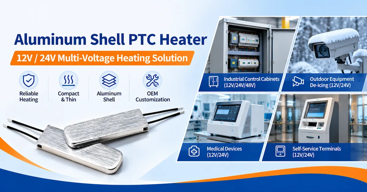
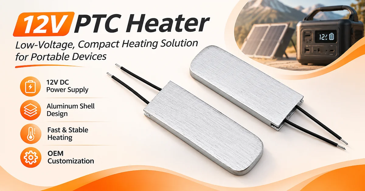
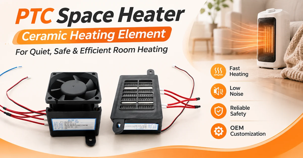
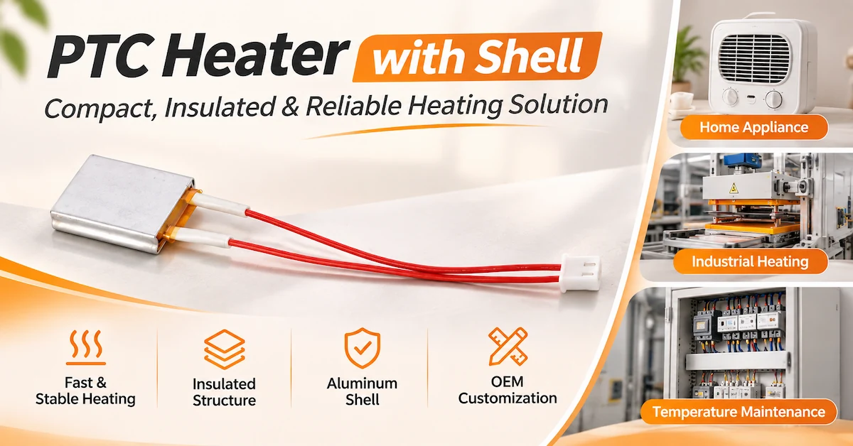
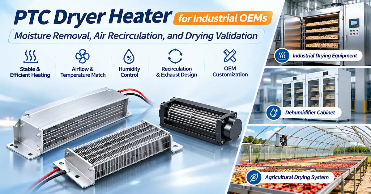
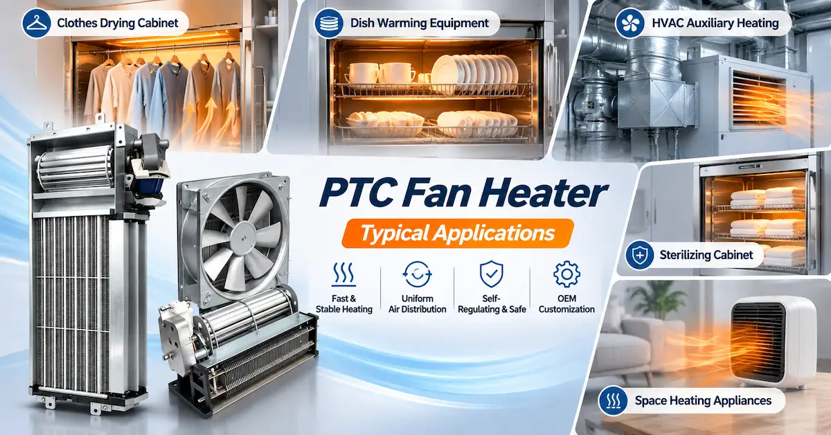
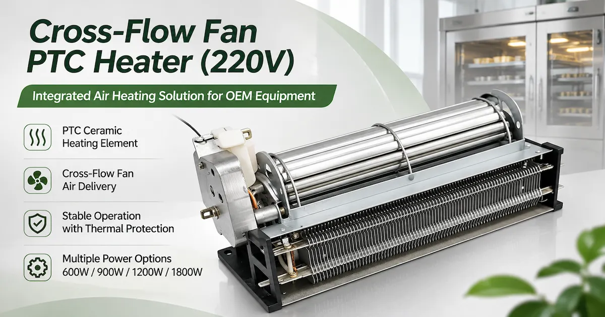
Dongguan Tianrui Electronics Co., Ltd. offers several PTC air-heating components for OEM evaluation, including integrated fan-heater arrangements.
This article focuses on their electrical integration and abnormal-condition validation, rather than airflow optimization or fan architecture selection.
For those separate topics, see Tianrui's PTC Fan Heater: Axial vs. Cross-Flow Guide and PTC Air Heater Fan Curve Matching Guide.
What Are the Electrical Components of a 220V PTC Fan Heater?
A PTC heater with fan combines several electrical functions that must be evaluated separately.
The heating element generates thermal energy.
The fan motor moves air through the heating structure.
The control system decides when heating is permitted.
Protective devices address defined electrical or thermal hazards.
Table 1. Electrical Subsystems in a 220V PTC Fan Heater
| Subsystem | Primary Function | OEM Verification Requirement |
|---|---|---|
| PTC heating core | Converts electrical input into heat | Rated voltage, power behavior, startup current, insulation |
| Fan motor | Moves air through the heating assembly | Rated supply, starting current, operating status, failure behavior |
| Heater switching device | Connects or disconnects heating power | Current capability, load suitability, switching endurance |
| Fan switching device | Controls fan operation | Motor-load rating, startup characteristics |
| Control electronics | Coordinates heating and fan operation | Operating sequence, fault handling, restart logic |
| Fan or airflow monitoring | Detects loss of required cooling airflow | Detection method, failure thresholds, response |
| Temperature sensor | Monitors relevant system temperatures | Sensor accuracy, placement, open/short fault behavior |
| Independent thermal protection | Provides a separate protective response when required | Location, operating characteristic, interruption capability |
| Input protection and wiring | Supports safe electrical distribution | Ratings, conductor sizing, insulation, protection coordination |
Heater and fan power must be identified separately
A product marketed as a 220V PTC fan heater does not necessarily use one electrically identical supply for every internal component.
Possible architectures include:
-
A 220V heater with a separately supplied fan motor.
-
A fan and heater both rated for the same nominal AC voltage.
-
A mains-powered heating assembly with low-voltage control electronics.
The exact arrangement depends on the selected product.
OEMs should request the wiring diagram rather than assuming that the fan can be connected directly to the heater's rated supply.
Control and power circuits have different responsibilities
The control circuit may process temperature information, user commands, and fan-status signals.
The power circuit carries the electrical load of the heater and motor.
An electrically isolated controller can improve the separation of low-voltage electronics from hazardous live circuits where required by the design.
However, isolation and protective architecture must be verified rather than assumed from the presence of a controller.
How Should Startup Current Affect Relay or Switching Device Selection?
A PTC heating element changes resistance as its temperature changes.
Its electrical current during initial energization can therefore differ from the current after thermal stabilization.
The fan motor also has its own starting characteristics.
Both loads must be evaluated when selecting contactors, relays, semiconductor switches, wiring, and protective devices.
Why nominal wattage is insufficient
A simple electrical estimate for a 1200W load at 220V is:
I ≈ P / V = 1200 / 220 ≈ 5.45A
This is only an illustrative power-to-current estimate.
It does not establish the actual maximum current of a PTC ceramic heater during startup.
Tianrui's MZ11 PTC Fan Heater product page publishes the following model information.
Table 2. Selected Tianrui MZ11 Published Electrical Ratings
| Model | Rated Voltage | Listed Power | Listed Maximum Surge Current |
|---|---|---|---|
| MZ11-08A1 | 220V | 800W | 7.3A |
| MZ11-10A1 | 220V | 1000W | 9.1A |
| MZ11-12A1 | 220V | 1200W | 10.5A |
| MZ11-30A1 | 220V | 1600W | 14.6A |
These values are reproduced from the published product specifications.
Important:
The public table does not establish a complete current-versus-time waveform or all measurement conditions. The figures should not be treated as a universal relay-sizing rule or as verified current curves for other Tianrui assemblies.
What should engineers request?
Before selecting the heater switching device, request:
-
Maximum expected current under defined supply and thermal conditions.
-
Current-versus-time measurements during startup.
-
Stabilized current and power.
-
Required switching frequency and expected operating cycles.
-
Electrical supply tolerance and frequency.
-
Fan-motor starting current.
-
Relevant switching-device load ratings.
-
Available protection coordination information.
Mechanical relays versus semiconductor switches
Electromechanical relays may be appropriate where their contact ratings, electrical endurance, insulation, and load characteristics satisfy the application.
However, a relay can fail with welded or stuck contacts.
Semiconductor switching devices may provide different switching characteristics, but they introduce their own requirements, including heat dissipation, leakage current, and short-circuit failure considerations.
A solid-state switch should not automatically be treated as providing physical isolation when it is commanded off.
The appropriate switching solution depends on the load and the complete equipment safety design.
Why the fan must be considered separately
A switching device suitable for a PTC heating element is not automatically suitable for the fan motor.
Motor starting behavior and switching requirements may differ from those of a predominantly resistive heating load.
Where heater and fan share an upstream protective device, their combined electrical behavior must also be evaluated.
OEM approval criterion:
The selected switching devices must be verified for the actual load conditions, not merely chosen using the heater's nominal wattage.
Why Does Fan-Failure Detection Matter for a PTC Air Heater with Fan?
A PTC air heater with fan relies on moving air to transfer heat from the heating structure to the intended environment.
When airflow falls or stops, the thermal balance changes.
The PTC ceramic may become hotter, increasing its resistance and reducing its electrical power.
However, this does not prove that the complete assembly remains within safe temperature limits.
Nearby wiring, plastic housings, mounting components, insulation, or accumulated dust may experience different temperatures from the ceramic itself.
A fan command is not proof of airflow
A controller may command the fan to operate while the motor is disconnected, stalled, or mechanically obstructed.
Similarly, a powered fan motor does not necessarily deliver adequate airflow.
Different monitoring approaches provide different information.
Table 3. Fan-Failure Detection Methods and Limitations
| Monitoring Method | What It Can Indicate | Important Limitation |
|---|---|---|
| Fan command status | Controller requests fan operation | Does not prove rotation |
| Fan tachometer | Fan rotational speed | Rotation does not guarantee adequate airflow |
| Motor-current monitoring | Electrical behavior of motor circuit | Current alone may not identify every airflow restriction |
| Airflow or pressure sensing | Air movement or pressure condition | Requires validated sensor location and threshold |
| Heater or duct temperature sensing | Thermal response to operating conditions | May detect a problem after temperatures have begun rising |
What should determine the monitoring method?
The required monitoring approach depends on the consequences of inadequate airflow.
For some equipment, fan-speed monitoring combined with temperature protection may be appropriate.
Other applications may require a more direct indication of airflow.
A temperature sensor should also be evaluated for its response time and thermal location.
The OEM must determine whether the selected detection method can identify the relevant failure modes early enough to satisfy the equipment's protection requirements.
How Can OEMs Design Fan and Heater Operating Interlocks?
The central engineering requirement is that heater operation must be permitted only when the necessary operating and protective conditions are satisfied.
An interlock is a control relationship that prevents or stops heating when specified conditions are not met.
The exact circuit implementation depends on the intended equipment and applicable safety requirements.
Recommended functional sequence
A conceptual heating sequence can be organized into the following states.
Table 4. PTC Fan Heater Functional Interlock Logic
| System State | Fan Command | Heater Permission | Required Condition or Response |
|---|---|---|---|
| Idle | Off or application-defined | Disabled | No heating request |
| Fan startup | On | Disabled | Establish the required fan-operating condition |
| Fan verified | On | Eligible for enable | Fan and protection checks satisfied |
| Normal heating | On | Enabled | Monitor fan status and temperature |
| Fan failure detected | Application-defined | Disabled | Initiate defined fault response |
| Overtemperature detected | Application-defined | Disabled | Activate the applicable protective response |
| Heating demand ends | Continue if required | Disabled | Complete validated cooldown sequence |
| Controller power failure | Cannot be assumed available | Disabled by safe-state design | Heating must not depend on an unverified software state |
| Fault reset | Application-defined | Disabled until conditions verified | Apply approved restart policy |
This table is a conceptual OEM design template, not a published Tianrui control circuit or a substitute for safety engineering.
Interlock 1: Fan verification before heating
The controller should not enable the heater until the required fan-operating condition has been established.
The condition may be defined using speed, airflow, or another validated method.
A fixed startup delay alone does not establish that the fan is functioning.
Interlock 2: Continuous monitoring during heating
A fan that starts correctly can fail later.
The control system should evaluate relevant fan-status and temperature information during operation.
Loss of the required condition should initiate the defined heater shutdown response.
Interlock 3: Defined cooldown behavior
Some equipment may require the fan to continue operating after the heating element is switched off.
Whether this is necessary, and for how long, must be determined through testing.
A cooldown sequence cannot be relied upon when the fan itself has failed or when its supply is unavailable.
Interlock 4: Fault recovery and restart
The equipment should have a defined restart policy.
An automatically restarting controller must not re-energize the heater while a hazardous fault remains.
Where manual reset, a latched fault, or another recovery procedure is required, this must be incorporated into the design.
Interlock 5: Independent protection against control failure
Software interlocks alone may not address every foreseeable failure.
For example, a controller may command the heater off while a switching component remains electrically closed.
An appropriately designed independent protective device may therefore be necessary.
The key question is not only whether the controller can detect a fault, but whether the complete system can place the heating circuit into its required safe condition.
What Happens If the Fan Stops but the Heater Remains Energized?
Fan stoppage changes how heat is removed from the PTC element.
The consequences depend on the ceramic characteristic, supply voltage, enclosure, mounting structure, residual convection, and nearby materials.
Possible thermal consequences
-
Increased heating-element temperature.
-
Higher temperatures at local mounting points.
-
Reduced heat transfer to the intended airflow.
-
Elevated temperatures near connectors and wiring.
-
Hotspots in adjacent enclosure materials.
-
Unexpected operation of a thermal protective device.
PTC self-regulation may reduce electrical input under these conditions.
It does not guarantee that the surrounding assembly will remain below every applicable temperature limit.
Why “the PTC cannot overheat” is not a sufficient safety claim
The operating temperature of the ceramic is not the only relevant safety measurement.
A nearby plastic bracket, cable sheath, or confined surface may have a different permissible temperature.
In addition, the complete equipment may contain other heat sources or abnormal conditions.
The manufacturer must verify the assembled system rather than infer safety from the ceramic's resistance-temperature characteristic.
What should a fan-stop test demonstrate?
A defined fan-loss test should establish:
-
Whether the fault is detected.
-
Whether the heater receives a shutdown command.
-
Whether the heating power is actually interrupted.
-
Whether surrounding materials remain within their applicable limits.
-
Whether independent thermal protection operates when needed.
-
Whether the equipment's restart behavior is acceptable.
These observations should be documented using representative operating and installation conditions.
Fault tests involving energized mains equipment should be conducted by qualified personnel in an appropriately controlled laboratory.
How Should Overtemperature Protection Be Verified?
A temperature sensor may help the controller regulate heating or detect abnormal conditions.
However, a sensor-based control function and an independent thermal protective device are not necessarily equivalent.
Normal temperature control
A thermostat or electronic sensor may regulate the heater during ordinary operation.
Its location and calibration should correspond to the temperature being controlled.
Abnormal temperature protection
Thermal protection addresses conditions in which the equipment exceeds a defined safe operating limit.
Depending on the application, this may involve a temperature limiter, thermal cutoff, or another protective arrangement.
Independent protection
Where required by the safety design, an independent thermal protector must remain effective even if the primary controller or switching device fails.
For example, a control sensor that shares the same power supply and processing logic as the main controller may not provide an independent protective layer.
Temperature-measurement locations
A system qualification plan may include:
-
Heating-element surface.
-
Air outlet.
-
Fan motor.
-
Mounting brackets.
-
Wiring terminals.
-
Connector bodies.
-
Adjacent plastic enclosure.
-
Other temperature-sensitive components.
The appropriate measurement positions depend on the actual equipment construction.
How should a thermal protector be selected?
The engineering team should confirm:
-
Operating-temperature characteristic.
-
Tolerance and response behavior.
-
Electrical interruption rating.
-
Mounting location.
-
Thermal coupling.
-
Reset behavior.
-
Expected service conditions.
-
Relevant appliance safety requirements.
The activation point must be compatible with the permitted temperatures of the materials and assembly.
No universal cutoff temperature can be assigned to every 220V PTC fan heater.
What Electrical Insulation and Grounding Checks Are Needed?
A nominal 220V heating assembly requires careful evaluation of its electrical insulation, wiring, accessible surfaces, and protective architecture.
The exact requirements depend on whether the finished equipment uses protective earthing, double or reinforced insulation, or another permitted construction.
Insulation and dielectric verification
The OEM should evaluate relevant insulation resistance and dielectric withstand requirements using the appropriate equipment standard and test conditions.
A supplier's insulation-resistance value for an individual component should not automatically be treated as approval for the entire appliance.
Clearance and creepage
Electrical separation must be assessed across relevant live parts, circuits, surfaces, and insulating structures.
Required distances depend on the applicable design conditions and standards.
Protective earthing
For equipment requiring protective earthing, accessible conductive parts and protective connections must be evaluated as applicable.
For equipment designed using an appropriate double-insulation architecture, requirements differ.
It would be incorrect to assume that every PTC fan heater needs the same grounding arrangement.
Wiring and connectors
Electrical integration should also review:
-
Conductor current rating.
-
Temperature rating of insulation.
-
Terminal retention.
-
Cable routing near hot surfaces.
-
Strain relief.
-
Connector compatibility.
-
Mechanical protection against abrasion.
-
Relevant moisture and environmental exposure.
Applicable standards and their scope
Three IEC publications provide relevant references for appropriate applications:
1. IEC 60335-1:2020
This standard covers general safety requirements for household and similar electrical appliances within its defined scope.
It is relevant when evaluating applicable appliance-level electrical and abnormal-operation safety requirements.
2. IEC 60335-2-30:2009, with Amendments 1:2016 and 2:2021
This publication addresses particular safety requirements for room heaters, including fan heaters.
It is relevant when the completed equipment falls within that appliance category.
It should not automatically be applied as the sole product standard for a heater incorporated into a different appliance.
3. IEC 60730-1:2022
This publication addresses automatic electrical controls used in or associated with household and similar equipment, including aspects of control safety and testing.
It may be relevant to heater-control and protective-control functions within its scope.
Important:
Referencing these standards does not imply that Tianrui's components or a finished OEM appliance have obtained any specific certification. The applicable standard edition, national adoption, and compliance route must be determined for the target equipment and market.
220V PTC Fan Heater Fault-Test Matrix for OEM Approval
This matrix is the main engineering tool for qualifying a PTC fan heater 220V assembly.
It is intended to help OEM teams define abnormal operating conditions, expected protective responses, and documentary evidence.
Tests must be adapted to the applicable equipment design and standard.
Table 5. OEM Electrical and Thermal Fault-Test Matrix
| Fault Scenario | Main Risk | Required OEM Verification | Expected Protective Objective |
|---|---|---|---|
| Fan does not start | Heating without required airflow | Startup interlock and fan monitoring | Prevent heater enable until required conditions are met |
| Fan stops during heating | Reduced heat removal | Detection, heater switching, temperature measurements | Initiate safe fault response |
| Air inlet obstructed | Insufficient cooling | Installed airflow restriction and hotspot checks | Maintain applicable temperature limits or activate protection |
| Air outlet blocked | Local heat accumulation | Outlet and nearby material temperatures | Verify abnormal-operation response |
| Heater relay contacts remain closed | Continuous heater energization | Independent protective path | Prevent a hazardous outcome despite failed primary switching |
| Temperature sensor open circuit | Missing or invalid feedback | Controller fault detection | Avoid uncontrolled heating |
| Temperature sensor short circuit | Incorrect feedback | Controller response and diagnostic logic | Apply defined protective action |
| Fan-status signal lost or invalid | Incorrect fan-state information | Monitoring and fallback logic | Prevent unsafe heater operation |
| Supply outside normal operating condition | Changed electrical and thermal behavior | Defined supply variation tests | Meet specified operating and protective requirements |
| Controller restart or reset | Unexpected re-energization | Power-cycle and restart testing | Prevent heating before conditions are revalidated |
| Thermal protective device operates | Heating interruption | Protective-device operation and final circuit condition | Achieve required protected state |
| Wiring or connector fault | Loss of continuity, heating, or electrical hazard | Appropriate electrical and mechanical tests | Verify protection and fault containment |
How to use the matrix
For every relevant row, the OEM should specify:
-
Initial condition: Supply, temperature, operating mode, and installation.
-
Fault condition: Precisely defined abnormal event.
-
Measurement points: Electrical and thermal quantities to be recorded.
-
Required response: Acceptable control or protective outcome.
-
Acceptance limit: Derived from the equipment design and applicable standard.
-
Result: Measured evidence and pass/fail decision.
Table 6. Reusable Fault-Test Record
| Test ID | Initial Condition | Fault Applied | Electrical Response | Maximum Relevant Temperature | Protection Result | Pass/Fail |
|---|---|---|---|---|---|---|
| FT-01 | ______ | Fan non-start | ______ | ______ | ______ | ______ |
| FT-02 | ______ | Fan stops during heating | ______ | ______ | ______ | ______ |
| FT-03 | ______ | Outlet restriction | ______ | ______ | ______ | ______ |
| FT-04 | ______ | Heater switching failure | ______ | ______ | ______ | ______ |
| FT-05 | ______ | Temperature feedback fault | ______ | ______ | ______ | ______ |
| FT-06 | ______ | Defined supply abnormality | ______ | ______ | ______ | ______ |
This worksheet is a proposed qualification tool.
It is not a Tianrui factory test report, and it does not establish that any listed product has passed these fault scenarios.
Why should different faults be tested separately?
A fan-stop test cannot substitute for a blocked-outlet test.
A heater switch that fails closed presents a different problem from a temperature sensor that fails open.
Similarly, a thermal cutoff may respond to a hotspot that the controller's normal temperature sensor does not detect.
A complete fault plan should account for the distinct failure modes relevant to the design.
Which Tianrui 220V PTC Fan Heater Assemblies Can Be Evaluated?
Tianrui Electronics publishes several 220V PTC heater configurations that can serve as starting points for OEM engineering discussions.
The listed products differ in their heating arrangements and published power options.
Table 7. Tianrui 220V PTC Heating Products for OEM Review
| Product | Published Voltage | Published Power | Electrical Integration Consideration |
|---|---|---|---|
| 200W Mini PTC Air Heater with Fan | 220V | 200W | Verify dual-fan electrical supply, startup behavior, and protection |
| Cross-Flow Fan PTC Heater | 220V | 600W, 900W, 1200W, 1800W | Confirm fan-motor supply, heater switching, thermal protection |
| MZ11 PTC Fan Heater Series | 220V | 800–4000W listed across models | Confirm exact heater-model current and application-specific fan integration |
1. 200W Mini PTC Air Heater with Fan
The 200W 220V Mini PTC Air Heater with Fan is publicly listed as a compact heating assembly with a ceramic heating element and dual-fan arrangement.
For OEM integration, confirm:
-
Actual heater and fan electrical ratings.
-
Fan startup and operating behavior.
-
Required heater-permission conditions.
-
Available overtemperature protective components.
-
Thermal performance under defined fan faults.
The public description includes safety-related claims, but these should not replace application-specific verification.
2. 600W–1800W Cross-Flow Fan PTC Heater
Tianrui's 220V Cross-Flow Fan PTC Heater is listed with power options of 600W, 900W, 1200W, and 1800W.
Its integrated fan-heater construction may be relevant to warming cabinets, drying equipment, and other warm-air applications.
Before selecting a variant, request confirmation of:
-
Heater electrical input versus fan input.
-
Fan control and monitoring interfaces.
-
Electrical connection arrangement.
-
Thermal protection options.
-
Fault-test requirements for the intended enclosure.
3. MZ11 PTC Fan Heater Series
The MZ11 PTC Fan Heater Series lists multiple 220V heater models, including published power and maximum surge-current values.
These figures can support initial electrical discussions.
However, model-specific startup measurements and fan-system integration requirements must still be confirmed.
Why application data matters more than catalog power alone
A nominally identical heater may behave differently when installed in a different enclosure or control architecture.
For example, one OEM appliance may detect fan speed, while another may require airflow verification and independent thermal shutdown.
The correct component and protection concept should therefore be evaluated against the final equipment's requirements.
What should OEM buyers include in a technical RFQ?
Table 8. 220V PTC Fan Heater OEM Sourcing Checklist
| RFQ Item | Information to Provide |
|---|---|
| Application | Appliance type and intended market |
| Heater voltage | Nominal and permitted supply range |
| Heater power | Requested rating and test conditions |
| Fan supply | Voltage, current, motor type |
| Startup conditions | Available current and switching requirements |
| Control architecture | Controller type and proposed switching method |
| Fan monitoring | Tachometer, airflow sensor, or other method |
| Fault response | Required heater shutdown and restart behavior |
| Overtemperature protection | Monitoring and independent protection requirements |
| Electrical insulation | Relevant equipment class and safety requirements |
| Mechanical installation | Dimensions, mounting, enclosure |
| Wiring | Leads, connectors, grounding requirements |
| Qualification | Fault scenarios, temperature limits, test records |
| Sampling | Engineering evaluation quantity |
| Procurement | Expected production quantity and delivery market |
Example OEM Technical Inquiry
Subject: 220V PTC Fan Heater — Electrical Interlock and Fault-Protection Review
We are evaluating a 220V PTC fan heater for an OEM heating appliance.
Our project requires confirmation of the heater's electrical input, fan supply, startup current, switching-device requirements, and thermal-protection arrangements.
The equipment design includes fan monitoring and a defined response to fan failure or abnormal temperature conditions.
We can provide the application drawing, electrical architecture, installation dimensions, target operating conditions, and estimated purchasing quantity.
Please advise:
-
Which Tianrui 220V fan-heater configurations are suitable for engineering evaluation.
-
Which electrical specifications are available for the selected heater and fan.
-
Whether startup-current data can be provided.
-
What wiring, fan-control, and protective-device information is available.
-
Whether application-specific integration requirements can be reviewed.
-
What samples and supporting technical documents are available.
-
What commercial terms apply to the proposed configuration.
We would like to complete electrical and thermal compatibility testing before production approval.
To discuss a project, contact Tianrui Electronics with your proposed application and technical requirements.
Frequently Asked Questions About 220V PTC Fan Heater Protection
1. Is a PTC fan heater 220V automatically safe if the fan stops?
No.
PTC self-regulation may reduce heating power as the ceramic temperature rises, but it does not prove that nearby materials remain within safe temperature limits.
The finished equipment should be evaluated under relevant fan-failure and restricted-airflow conditions.
2. Does a PTC heater with fan need an interlock?
The need and design of an interlock depend on the appliance's hazard assessment and applicable requirements.
Where safe heating depends on fan operation, an appropriate control relationship should prevent or stop heating when required fan conditions are not satisfied.
3. Does the fan in a 220V PTC heater always operate at 220V?
No.
A 220V heater designation does not necessarily establish the fan motor's supply voltage.
The OEM must verify the fan specification and the complete electrical wiring arrangement.
4. How should a relay be selected for a PTC air heater with fan?
Relay selection should consider the heater's actual startup and operating currents, switching frequency, electrical load type, endurance requirements, and relevant failure conditions.
Fan-motor starting characteristics should be evaluated separately.
Nominal wattage alone is insufficient.
5. Can a solid-state relay provide the required heater isolation?
Not automatically.
Semiconductor switching devices can exhibit leakage current and different failure characteristics from mechanical contacts.
Where physical isolation or independent disconnection is required, the protective architecture must provide the appropriate function.
6. Is a single temperature sensor enough for fan-failure protection?
Not necessarily.
A temperature sensor may detect excessive heating, but response depends on placement and thermal conditions.
Some systems may need fan-status monitoring, airflow sensing, or independent protection.
The appropriate approach should be established through a documented safety analysis.
7. What happens when the heater relay fails in the closed position?
The heater may remain energized despite an off command from the controller.
The OEM must evaluate whether independent protective measures can prevent an unacceptable outcome.
A software shutdown command alone cannot interrupt current through welded relay contacts.
8. Should the fan continue operating after heater shutdown?
Some designs use post-heating fan operation to remove stored heat.
The need for continued fan operation and its duration should be determined through equipment testing.
A cooldown strategy must not assume fan operation is available during a fan failure.
9. Which IEC standards apply to 220V PTC fan heaters?
The applicable standard depends on the complete equipment.
IEC 60335-1 addresses general household and similar appliance safety. IEC 60335-2-30 addresses room heaters within its scope. IEC 60730-1 addresses relevant automatic electrical controls.
Other equipment-specific requirements may apply.
10. What should an OEM request before ordering a custom 220V PTC fan heater?
Request the selected product's electrical specifications, heater and fan ratings, available startup-current information, wiring documentation, dimensions, protection requirements, and agreed sample-testing criteria.
Include the application's intended supply range, operating conditions, safety requirements, and expected order volume.
Conclusion
Integrating a PTC fan heater 220V into an OEM product requires coordinated electrical, thermal, and control-system engineering.
The ceramic heating element is only one part of the system.
The fan motor, switching components, sensors, wiring, and protective devices must operate together under normal conditions and respond appropriately to foreseeable faults.
For appliance manufacturers and electrical engineers, the key qualification priorities are:
-
Confirm separate electrical ratings for the heater and fan.
-
Measure startup and operating current before finalizing switching devices.
-
Verify fan-operation interlocks before and during heating.
-
Define a safe response to fan stoppage and blocked airflow.
-
Evaluate independent protection against switching and control failures.
-
Test electrical insulation and relevant grounding arrangements within the complete appliance.
-
Use a structured fault-test matrix to record abnormal-condition results.
-
Approve the final assembly using documented engineering and procurement criteria.
A PTC heater with fan may simplify warm-air equipment integration, but it does not eliminate the OEM's responsibility to verify electrical and thermal behavior.
Likewise, a PTC air heater with fan cannot be considered fault-safe solely because its ceramic element is self-regulating.
Dongguan Tianrui Electronics Co., Ltd. offers 220V PTC heater and fan-heater configurations for appliance and equipment applications.
The company's published product range provides a starting point for selecting a heating assembly and discussing project-specific electrical and mechanical requirements.
Need a 220V PTC Fan Heater for an OEM Appliance?
Explore Tianrui's PTC Fan Heater Products or contact Tianrui Electronics to discuss heater and fan ratings, electrical integration requirements, protection concepts, engineering samples, and OEM sourcing.
For a productive technical review, send your supply requirements, heater power, fan specifications, proposed switching architecture, fault-response requirements, mechanical drawings, and expected order quantity.
Email:
Phone:
+86 135 3277 2961
A verified heater specification, well-defined interlock strategy, and documented electrical fault-validation plan provide a stronger foundation for reliable OEM heating equipment and long-term component procurement.