Choosing a PTC thermistor for an industrial product begins with a question that is often overlooked: What exactly should the component do when the temperature or current changes?
A motor manufacturer may need a sensor that detects winding overheating and signals a protection relay. A power supply designer may need a component that limits current during an overload. A compressor manufacturer may use a PTC device to control current through an auxiliary starting winding. Although these applications all involve positive temperature coefficient thermistors, they do not require the same electrical characteristics.
For OEM engineers and industrial buyers, the correct PTC thermistor must match the protection function, resistance-temperature characteristic, operating voltage, switching temperature, current requirements, and installation conditions. A component that performs reliably in one circuit may be unsuitable for another, even when both are described as PTC thermistors.
This guide explains how to distinguish the major PTC technologies, compare available component families, review important specifications, and prepare an effective request for quotation (RFQ). It also examines practical selection considerations for motor protection, industrial equipment, power supplies, and custom electronic assemblies.
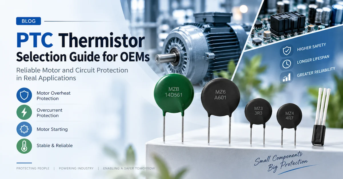
1. What Is a PTC Thermistor, and How Does It Work?
A PTC thermistor is a temperature-sensitive resistor whose resistance increases as its temperature rises. PTC stands for positive temperature coefficient, describing the relationship between temperature and electrical resistance.
However, not all PTC thermistors exhibit the same resistance-temperature behavior.
Certain ceramic PTC thermistors maintain a relatively moderate resistance below a characteristic switching region. Once the temperature reaches that region, resistance increases sharply, potentially by several orders of magnitude.
Other PTC devices, particularly silicon-based temperature sensors, have a smoother and more predictable resistance-temperature relationship. These are designed primarily for measuring temperature rather than acting as abrupt protection switches.
How the switching behavior works
For a switching-type ceramic PTC thermistor, the process can be explained in four stages:
-
Normal operation: The component remains within its intended resistance range while circuit current or surrounding temperature stays below the switching condition.
-
Temperature increase: Current-generated heat, external heating, or both raise the component temperature.
-
Resistance transition: Resistance rises sharply near the switching region, reducing current in a suitable series-protection circuit or providing a detectable signal to a controller.
-
Cooling and recovery: When the fault is removed and the component cools sufficiently, its resistance can return toward its original state.
This behavior can reduce the need for mechanical switching components in some designs. It does not mean that a PTC thermistor can independently replace every fuse, relay, or electronic protection circuit.
For example, a motor winding temperature sensor normally requires a compatible evaluation relay or control module. Its resistance change signals an abnormal temperature; the external protection system performs the motor shutdown.
Similarly, an overcurrent-limiting PTC often allows some residual current while in its high-resistance state. It should not be treated as a galvanic isolation device.
The distinction matters when specifying protection systems for industrial machinery, motors, household appliances, and electrical controls.
For a general overview of Tianrui's technology and available functions, see the PTC Thermistor Solution.
2. Which Type of PTC Thermistor Does Your Application Need?
The term "PTC thermistor" covers several product categories. Selecting by function is more reliable than selecting by appearance, diameter, or nominal resistance alone.
| PTC thermistor type | Primary function | Typical application | Main selection priority |
|---|---|---|---|
| Motor protection PTC | Detect excessive winding temperature | Industrial motors, pumps, compressors | Rated response temperature and relay compatibility |
| Overcurrent protection PTC | Increase resistance during abnormal current conditions | Power supplies, electronic circuits | Voltage, normal current, switching current, response time |
| Motor starting PTC | Reduce auxiliary-winding current after startup heating | Single-phase induction motors, compressors | Cold resistance, heating behavior, restart conditions |
| Preheating PTC | Control preheating current during lamp startup | Fluorescent lamps and electronic ballasts | Preheating resistance, timing, voltage rating |
| Silicon PTC sensor | Measure temperature through a predictable R–T relationship | Industrial controllers and electronic equipment | Resistance curve, tolerance, operating temperature |
| Composite PTC protection component | Combine PTC current limiting with another protection element | Smart meters, power electronics | Coordination between protection functions |
Why these types should not be interchanged
Consider two components with the same nominal resistance at 25°C.
One may be a switching-type ceramic PTC intended to transition rapidly into a high-resistance condition. The other may be a silicon PTC sensor designed to change resistance gradually for accurate measurement.
The room-temperature resistance could appear similar, but their behavior at 80°C, 100°C, or 150°C may differ substantially.
A motor temperature protection circuit requiring a particular switching response cannot be redesigned around a linear sensor without checking the control electronics.
Likewise, a PTC thermistor intended for motor starting may not provide the correct current-limiting characteristics for a continuously powered electronic circuit.
OEM purchasing teams should identify the required function before asking suppliers for resistance or diameter options.
Tianrui's PTC Thermistor Product Category includes switching, protection, and silicon-based sensing products, allowing buyers to begin with the appropriate application family.
3. Comparing Tianrui PTC Thermistor Product Families
Different Tianrui product series address different electrical and thermal requirements.
The following comparison summarizes publicly listed product information. Values refer to the relevant product pages and their available model ranges, not to every PTC thermistor sold by the company.
| Product family | Published example specifications | Primary application | Important purchasing consideration |
|---|---|---|---|
| MZ6 Motor Protection PTC | Tk: 60–180°C; published maximum working voltage: 30V | Motor winding overheating protection | Confirm single/triple sensor configuration and protection relay |
| MZB Overcurrent Protection PTC | R25: 1–1500Ω ±30%; listed maximum voltage: 265V | Circuit overcurrent and overtemperature protection | Confirm exact part's hold/trip behavior and voltage |
| MZ4 PTC | R25: 600–800Ω ±25%; nominal diameter: 4mm | Electronic ballast and lamp preheating | Confirm the selected voltage and switching characteristic |
| MZ3 PTC | 3mm preheating-type device; multiple listed variants | Electronic ballasts and energy-saving lamps | Request the finalized part-specific resistance specification |
| Motor Starting PTC | R25: 30–60Ω ±25%; listed diameter: 9mm | Single-phase motor starting | Confirm startup duration, current, and cooling time |
| KTY Silicon PTC | Selected 1kΩ and 2kΩ nominal sensor variants | Continuous temperature measurement | Match the complete R–T characteristic and controller |
| Composite PTC | Combined PTC and varistor construction | Combined current and voltage protection | Evaluate the complete protection assembly |
These figures should be treated as initial selection references. Engineering buyers should request a datasheet or approved drawing for the exact proposed part number before design approval.
MZ6: Motor winding temperature protection
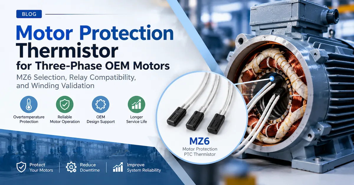
The MZ6 Motor Protection PTC Thermistor is intended for integration into motor thermal protection systems.
Tianrui publishes a rated action temperature range of 60–180°C for available versions. The appropriate selection depends on motor insulation, permissible winding temperature, installation location, and the characteristics of the connected protection relay.
A three-sensor assembly can be used to monitor the windings of a three-phase motor when connected to a compatible evaluation device.
MZB: Overcurrent and overtemperature protection
The PTC Thermistors for Overcurrent and Overheat Protection product page describes the MZB family.
Unlike a temperature-sensing device that reports winding temperature to a controller, an appropriately selected series-connected protection PTC can increase its resistance as current and self-heating rise.
Current rating, voltage rating, fault conditions, and thermal behavior must be evaluated together.
MZ3 and MZ4: Preheating applications
The MZ3 PTC Thermistor and MZ4 PTC Thermistor are associated with electronic ballast and preheating applications.
Their resistance and thermal characteristics influence the current available during lamp electrode preheating and the subsequent transition out of that operating condition.
They should not automatically be treated as interchangeable with motor winding protection sensors or general-purpose resettable circuit protectors.
Silicon PTC: Temperature measurement
Tianrui also lists KTY81, KTY82, KTY83, and KTY84 Silicon PTC Temperature Sensors.
These devices use silicon-based resistance-temperature behavior rather than the abrupt switching characteristic commonly associated with ceramic protection PTCs.
They are relevant when the controller requires a continuously varying electrical measurement of temperature.
4. Eight Technical Specifications to Verify Before Selecting a PTC Thermistor
The most important part of PTC thermistor procurement is understanding what each specification means in the intended circuit.
4.1 R25: Resistance at 25°C
R25 is the nominal resistance measured at 25°C under specified conditions.
For example, a PTC thermistor rated at 100Ω ±25% would have an accepted room-temperature resistance range of 75–125Ω, assuming that tolerance applies to the specified measurement condition.
That is an arithmetic example, not a specification for a particular Tianrui part.
A lower nominal resistance is not automatically better. In a current-carrying protection circuit, lower resistance may reduce normal operating voltage drop and power dissipation. In a temperature-sensing or preheating circuit, however, a different resistance value may be necessary for the correct electrical response.
The designer must also consider how the resistance changes with temperature and applied voltage.
4.2 Switching temperature and rated response temperature
For many ceramic PTC thermistors, a characteristic temperature region is associated with a rapid increase in resistance.
In motor temperature protection, a specified rated response temperature is often identified by Tk.
The most important question is not simply whether a component has a switching temperature of 120°C or 150°C. It is whether that response matches the allowable temperature of the protected equipment.
Suppose an OEM is developing a motor whose winding insulation must remain within a specified thermal limit.
The engineer needs to consider the insulation system, motor duty cycle, ambient temperature, winding hotspot distribution, and protection system response.
Selecting a switching temperature based only on the nominal insulation class may overlook differences between measured winding temperature and the hottest internal location.
A properly positioned thermistor should detect an unsafe thermal condition early enough for the complete protection system to respond.
4.3 Maximum operating voltage
Voltage rating is particularly important for PTC thermistors placed in series with an electrical load.
During normal operation, the voltage across the PTC may be relatively small. After the resistance increases sharply, the voltage across the component may approach a substantial portion of the supply voltage.
Therefore, selecting a device based only on its low-resistance operating condition can create a serious design error.
A useful design review should examine maximum continuous voltage, foreseeable voltage fluctuations, fault conditions, applicable AC/DC ratings, and the manufacturer's specified limitations.
Motor protection sensors require a different approach. A low-voltage sensor circuit connected to a protection relay should not be directly exposed to motor supply voltage simply because it is installed inside a high-voltage motor.
4.4 Normal current and switching current
For a current-limiting PTC thermistor, distinguish between the current that the component can carry without unwanted switching and the current that produces a high-resistance condition under stated conditions.
The ambient temperature affects this relationship.
A current level that is acceptable at 25°C may create excessive self-heating when the same component operates in a hot equipment enclosure.
This is why current ratings must be considered together with temperature derating information.
A useful selection rule is:
The protection component must remain stable at the highest expected normal operating current while responding appropriately to the lowest relevant fault current.
Both conditions need to be demonstrated by testing or reliable manufacturer data.
4.5 Response and switching time
PTC thermistors are thermally responsive devices.
Their response depends on the energy entering the component, heat loss to the surrounding environment, initial temperature, and package construction.
It is inappropriate to assume that every PTC thermistor switches within a fixed number of milliseconds.
For motor protection, response time is affected by the thermal connection between the winding and the sensor, as well as the evaluation relay.
For overcurrent protection, response time depends strongly on the magnitude of the fault current and the available voltage.
If a downstream component can tolerate a fault for only a short period, the designer must confirm that the PTC and the overall protection architecture act quickly enough.
4.6 Resistance-temperature curve
A single R25 value cannot fully describe a PTC thermistor.
Engineers may need a resistance-temperature curve or minimum and maximum resistance limits at specified temperatures.
For a winding protection sensor, resistance values below and above Tk help establish whether the evaluation relay will distinguish normal and abnormal conditions.
For a silicon PTC temperature sensor, the resistance-temperature relationship determines measurement accuracy and controller compatibility.
When replacing an existing sensor, compare the complete curve rather than only the nominal resistance.
4.7 Power dissipation and thermal environment
Electrical power dissipated in a resistive component can be expressed as:
P = I²R
where P is power in watts, I is current in amperes, and R is resistance in ohms.
This relationship helps explain why self-heating cannot be ignored.
However, a PTC thermistor's resistance changes with temperature, so a simple calculation using its room-temperature resistance does not describe the full transition or steady-state behavior.
Heat transfer through the PCB, enclosure, mounting material, surrounding air, or adjacent components must also be considered.
A component tested in open air may perform differently when installed inside a sealed enclosure.
4.8 Dimensions, terminals, and installation
Component dimensions affect more than PCB space.
In motor applications, the sensor must fit into the winding structure while maintaining electrical insulation and thermal contact.
For leaded circuit protection devices, engineers should evaluate lead spacing, body diameter, height, soldering conditions, mechanical support, and clearance from heat-sensitive components.
A replacement with matching resistance but different dimensions may introduce new thermal or mechanical problems.
5. How to Select a PTC Thermistor for Motor Winding Protection
Motor winding protection is one of the most important applications for temperature-sensitive switching PTC thermistors.
Industrial motors may experience overheating because of mechanical overload, restricted ventilation, voltage imbalance, phase loss, frequent starting, or unusually high ambient temperatures.
A conventional current-based overload protector may not directly measure winding temperature. A PTC sensor embedded near the windings provides thermal information from the protected area.
Step 1: Identify the motor's thermal requirements
Start by collecting the motor's insulation class, rated current, supply characteristics, duty cycle, maximum ambient temperature, and expected operating conditions.
Identify the permissible winding temperature and relevant protection requirements.
Different designs may require different thermal response points even when their power ratings are similar.
Step 2: Determine the necessary rated response temperature
Select the sensor response temperature in relation to the motor's thermal design.
Tianrui's MZ6 range includes different rated action temperature options. The appropriate Tk should be confirmed against the motor manufacturer's insulation and protection requirements.
Choosing an unnecessarily low response temperature can cause nuisance shutdowns.
Choosing an excessively high response temperature can delay the detection of overheating.
Step 3: Select the sensor configuration
A single sensor may be sufficient for a particular winding or localized temperature measurement.
Three-phase motor protection may use multiple sensors positioned in different windings, with the sensors connected in series to a compatible protection relay.
The series arrangement allows the evaluation system to detect a significant resistance increase caused by an overheated sensor.
The total resistance limits of the assembly must remain compatible with the selected relay.
Step 4: Review the installation location
Thermal contact is essential.
If the PTC sensor is installed in a cooler location than the critical winding hotspot, it may respond too late.
Conversely, unsuitable positioning near an unrelated external heat source may cause unnecessary shutdown.
Installation should also avoid damaging the sensing element or leads during motor winding and assembly operations.
Step 5: Match the evaluation relay
The PTC thermistor is one part of a complete protection circuit.
The control module must recognize the sensor's resistance transition and operate the appropriate alarm, contactor, or shutdown circuit.
Check the relay's permissible sensor resistance, measurement voltage, number of supported sensors, response thresholds, and fault-monitoring functions.
The designer should also establish whether automatic restart after cooling is acceptable. Many industrial systems require a deliberate restart procedure to avoid unexpected machinery movement.
Step 6: Validate the complete motor assembly
Testing should include normal rated operation, elevated ambient conditions, relevant overload scenarios, and verification that the protection circuit responds before unacceptable thermal conditions occur.
Where practical and safe, investigate the effect of restricted cooling or phase imbalance using a controlled engineering test procedure.
A thermistor with acceptable laboratory specifications is not automatically sufficient evidence that the finished motor meets its thermal protection requirements.
For detailed product information, review Tianrui's MZ6 PTC Thermistor for Motor Protection.
6. Selecting a PTC Thermistor for Overcurrent Protection
Overcurrent protection presents a different design problem.
Here, the PTC may be incorporated into the current path. Excessive current generates heat, which increases resistance and reduces current through the affected circuit.
This behavior is useful only when the protection component and surrounding circuit are properly matched.
Evaluate both normal operation and abnormal conditions
An OEM power electronics designer should define the current during continuous operation, expected startup current, short-duration transient current, and foreseeable fault current.
It is equally important to determine how these values change at different operating temperatures.
For illustration, consider a device that operates normally at 100mA but can reach 150mA under its highest expected legitimate load.
A possible fault could create a much higher current, depending on the source impedance and circuit arrangement.
The selected PTC would need to tolerate normal operation at the highest expected ambient temperature and respond appropriately to the specified fault.
These values form an illustrative engineering scenario, not a recommendation for any particular Tianrui part.
Check the fault voltage
During a protection event, a high-resistance PTC may have to withstand much of the available supply voltage.
Do not select a lower-voltage component solely because its R25 and nominal current appear suitable.
For AC systems, also verify the applicable voltage definition and operating frequency where relevant.
Consider startup and nuisance tripping
Some devices experience brief but legitimate inrush currents during startup.
A PTC component should not create unwanted shutdown every time a power supply charges its capacitors or a motor accelerates.
However, allowing a large startup current to pass should not compromise protection against a sustained fault.
Both the amplitude and duration of current pulses matter.
Check the residual fault current
A PTC in its high-resistance state does not necessarily produce zero current.
The remaining current and power dissipation must be compatible with the protected equipment, upstream protection, and thermal design.
Where required, provide a fuse, circuit breaker, electronic shutdown, or other protective device as part of the overall safety architecture.
Evaluate reset behavior
After the fault is removed, the PTC can cool and return toward a lower resistance.
Cooling time depends on the component and the environment.
If the supply remains connected, residual power may maintain the device at an elevated temperature.
For equipment that repeatedly cycles between fault and recovery, validate resistance stability and the allowable number of operating cycles.
Tianrui lists an MZB Series PTC for Overcurrent and Overheat Protection as an available starting point for this category.
A complete selection should still be based on the exact proposed part number, circuit conditions, and test data.
7. Motor Starting PTC vs Motor Protection PTC: What Is the Difference?
Motor starting and motor overheating protection are often confused during component sourcing.
Both may be associated with compressors, fans, pumps, and other electric motors, but the design requirements differ considerably.
Motor starting PTC thermistors
A motor starting PTC is used in a suitable starting circuit for a single-phase induction motor.
When initially cool, the component has a relatively low resistance that permits current through the auxiliary winding.
As current heats the PTC, its resistance increases substantially and the auxiliary-winding current decreases.
The switching behavior results from thermal changes within the component. It does not mean the PTC directly measures motor rotational speed.
Starting performance depends on supply voltage, winding impedance, cold resistance, heating rate, operating temperature, and cooling time between starts.
A compressor that restarts before its starting PTC has cooled sufficiently may not receive the required auxiliary-winding current.
Therefore, repeated-start testing is particularly important.
Tianrui offers a Motor Starting PTC Thermistor for relevant single-phase motor applications.
Motor protection PTC thermistors
A motor protection PTC, such as an appropriately specified MZ6 sensor, primarily responds to the temperature of the winding in which it is installed.
Its function is to provide a signal to the protection circuit when a thermal threshold is reached.
It is not intended to carry the starting-winding current in the manner of a motor starting PTC.
| Comparison | Motor Starting PTC | Motor Protection PTC |
|---|---|---|
| Main purpose | Control auxiliary-winding current | Detect excessive winding temperature |
| Typical location | Motor starting circuit | Thermally coupled to winding |
| Operating principle | Self-heating changes circuit current | Winding temperature changes sensor resistance |
| Main parameters | Cold resistance, heating time, voltage, reset time | Tk, resistance limits, thermal contact, relay compatibility |
| Main validation | Starting torque, repeated starts, duty conditions | Winding temperature and shutdown response |
| Interchangeable? | No | No |
For a motor OEM, purchasing the wrong type can create more than a component compatibility issue. It can affect the behavior of the entire starting or protection system.
8. When Should an OEM Choose a Silicon PTC Temperature Sensor?
Not every project requires an abrupt high-resistance transition.
An industrial controller may need to monitor temperature continuously, calculate a temperature value, and respond at multiple control thresholds.
In that situation, a silicon PTC temperature sensor may be more appropriate.
Switching PTC vs silicon PTC
A switching-type ceramic PTC is often useful for a defined temperature threshold or protective transition.
A silicon PTC provides a more gradual resistance-temperature relationship that can be used for measurement with suitable electronics.
For example, Tianrui's KTY-related product range includes selected models with nominal resistance values around 1kΩ or 2kΩ at 25°C.
The exact curve, nominal resistance, tolerance, temperature range, and package must be matched to the specific model.
An OEM replacing a KTY-type sensor should not assume that all nominally similar sensors use identical resistance curves.
Questions to ask before choosing
Determine whether the application needs a simple thermal alarm or actual temperature measurement.
If the controller must display 65°C, 80°C, or 100°C, for example, it needs an adequately characterized sensing relationship and suitable signal conversion.
If the equipment only needs a defined overtemperature signal to stop a motor, an appropriately selected switching sensor may simplify the sensing portion of the design.
Also consider self-heating caused by measurement current, the accuracy of the controller's conversion method, and resistance tolerance across the entire operating range.
Tianrui's Silicon PTC Temperature Sensor category provides examples of these measurement-oriented components.
9. PTC Thermistor vs NTC Thermistor vs Polymer PPTC
These components are frequently grouped under the broad term "thermistor," but they should not be treated as identical.
| Characteristic | Ceramic Switching PTC | NTC Thermistor | Polymer PPTC |
|---|---|---|---|
| Temperature effect | Resistance increases sharply near a characteristic region | Resistance generally decreases as temperature rises | Resistance rises sharply under thermal trip conditions |
| Typical use | Motor protection, switching, current limiting | Temperature measurement, compensation, power inrush limiting | Resettable overcurrent protection |
| Important parameters | R25, switching temperature, voltage, current | R25, B-value, R–T curve | Hold current, trip current, voltage, resistance |
| Normal circuit behavior | Depends strongly on component function | Depends on sensing or power-limiting design | Usually designed for relatively low resistance |
| After a fault | Recovery depends on cooling and circuit conditions | Generally returns along its thermal characteristic | Can reset after cooling, with possible post-trip resistance changes |
Why material technology matters
Ceramic PTC devices, silicon temperature sensors, and polymeric resettable devices rely on different material structures and electrical behavior.
A product page that describes a component as "resettable" does not establish whether it is ceramic or polymer-based.
The bill of materials should therefore identify the technology and an approved manufacturer part number.
This is particularly important for replacement sourcing, where a purchasing team may find multiple suppliers using similar generic descriptions.
Can a PTC thermistor replace an NTC thermistor?
Generally, not without redesigning the measurement or control circuit.
An NTC temperature sensor has a negative resistance-temperature coefficient, whereas a PTC sensor has a positive coefficient.
Controller calibration, bias circuitry, and fault interpretation may be completely different.
For projects using NTC sensing, Tianrui maintains a separate NTC Thermistor Product Category.
Selecting between PTC and NTC should be driven by the circuit function rather than assumptions about which technology is universally more reliable or accurate.
10. How Operating Environments Affect PTC Thermistor Selection
A PTC thermistor that meets its electrical specifications under laboratory conditions still needs to function within the finished product.
Environmental conditions can substantially change the component's response.
| Operating environment | Potential issue | Recommended engineering review |
|---|---|---|
| High ambient temperature | Reduced current margin or earlier operation | Evaluate temperature derating and worst-case normal load |
| Low ambient temperature | Longer heating time or different starting behavior | Test cold starts and required switching response |
| Motor winding installation | Thermal contact and insulation stress | Verify placement, insulation, and thermal response |
| High humidity | Leakage, corrosion, packaging degradation | Review enclosure, coating, and humidity testing |
| Vibration | Lead fatigue or damaged connections | Evaluate mechanical support and vibration exposure |
| Enclosed electronics | Heat accumulation | Test the component inside the actual enclosure |
| Repeated operating cycles | Resistance drift or cumulative stress | Conduct representative cycling and recovery tests |
| High-voltage circuits | Dielectric stress under fault conditions | Confirm maximum voltage and relevant insulation requirements |
| Adjacent heat sources | Unintended switching | Review component location and board thermal layout |
Industrial motors and compressors
Thermal cycling, vibration, and constrained installation space can affect winding-embedded thermistors.
The sensor assembly needs sufficient mechanical integrity without sacrificing the thermal connection required for timely detection.
Household appliances
Washing machines, dishwashers, hair-care equipment, and other household appliances may combine moisture exposure, heating, vibration, and frequent power cycling.
The acceptable component construction depends on whether the thermistor is mounted on a PCB, attached to a heating assembly, or integrated into a motor.
See Tianrui's Home Appliance Applications for related product application categories.
Industrial electronic equipment
Protection thermistors installed near transformers, power semiconductors, or power resistors may experience elevated local temperature even when the surrounding room is relatively cool.
Placement can affect both normal power loss and unwanted activation.
A suitable thermal design should account for the actual board and enclosure environment rather than relying only on room-temperature ratings.
Automotive and mobility electronics
Vibration, temperature cycling, and electrical transients introduce additional validation requirements.
A product's suitability for an automotive application must be assessed against the exact vehicle system and required component qualification.
A general industrial PTC designation does not automatically establish automotive-grade compliance.
11. PTC Thermistor Manufacturing, Materials, and Quality Control
For industrial OEM buyers, long-term performance depends on more than the nominal electrical specification.
Material formulation, manufacturing consistency, electrical contacts, encapsulation, and testing methods can influence device behavior.
Ceramic PTC manufacturing considerations
Many switching-type ceramic PTC thermistors use barium-titanate-based ceramic formulations.
Manufacturing typically involves preparing raw materials, mixing and processing the ceramic composition, shaping, sintering, forming electrodes, and adding the required leads or protective coating.
The electrical properties depend on the ceramic composition, microstructure, processing conditions, and the completed component construction.
Small manufacturing variations may affect initial resistance or switching behavior.
For that reason, a manufacturer should maintain appropriate process controls and test the electrical characteristics against an approved specification.
What should be included in a PTC thermistor QC plan?
An OEM quality review may include the following checks:
| Test or inspection | Purpose | Relevant product types |
|---|---|---|
| Resistance at specified temperature | Verify nominal electrical characteristics | All thermistor types |
| Resistance-temperature measurement | Verify switching or sensing behavior | Switching and silicon PTCs |
| Rated response temperature test | Confirm thermal protection threshold | Motor protection PTC |
| Current response test | Evaluate switching under defined electrical load | Overcurrent and starting PTC |
| Voltage withstand evaluation | Assess electrical robustness | Applicable power and protection PTCs |
| Insulation test | Verify insulation performance where required | Motor sensor assemblies |
| Thermal cycling | Investigate changes after repeated heating and cooling | Applicable PTC types |
| Mechanical and lead inspection | Check assembly integrity | Leaded and sensor assemblies |
| Dimensional inspection | Verify component fit | All packaged devices |
| Batch traceability review | Support production consistency and investigations | OEM production |
Not every test applies to every part number. Test conditions, sample size, acceptance criteria, and frequency should be determined by the actual product and customer requirements.
Standards and compliance documentation
Standards such as the IEC 60738 series are relevant to certain thermistor technologies. DIN 44081 and DIN 44082 are also commonly referenced for applicable motor protection temperature sensors.
However, a reference to a standard is not the same as independent certification or documented conformity of every product in a manufacturer's catalog.
Before approving a part, buyers should request the applicable specification, relevant test evidence, environmental compliance documents, and any certifications required by the finished equipment.
Avoid accepting generic statements such as "all international standards approved" without confirming the standard number, exact model coverage, and supporting documentation.
Why sample testing is necessary
A first article or sample can establish basic fit and electrical behavior.
It cannot, by itself, demonstrate long-term stability throughout volume production.
For recurring industrial orders, the purchasing and engineering teams should agree on the critical-to-quality characteristics, inspection methods, acceptable tolerances, and procedure for managing component changes.
This reduces the risk of receiving a nominally identical component with different performance in subsequent batches.
12. Common PTC Thermistor Selection Mistakes
Several recurring mistakes can cause unnecessary redesign, delayed production, or field failures.
Mistake 1: Selecting only by room-temperature resistance
Two products may have similar R25 values but different switching temperatures and thermal curves.
Better approach: Compare complete electrical characteristics and verify performance in the intended circuit.
Mistake 2: Treating every PTC as a resettable fuse
A motor temperature sensor, motor starting component, and overcurrent protection device are not interchangeable.
Better approach: Define whether the component should sense, switch, limit current, or control starting behavior.
Mistake 3: Ignoring maximum operating voltage
A protection component may experience substantially more voltage after it switches into a high-resistance condition.
Better approach: Evaluate voltage under fault conditions, not just normal operation.
Mistake 4: Assuming automatic recovery always restarts the equipment
The thermistor may recover electrically while the complete protection system remains latched off.
Alternatively, a continuously energized PTC may remain warm and highly resistive.
Better approach: Define recovery and restart behavior at system level.
Mistake 5: Ignoring the thermal installation
A motor winding sensor that is not thermally coupled to the protected winding cannot be relied upon to indicate the actual hotspot temperature.
Better approach: Validate installation position and thermal response within the finished motor.
Mistake 6: Using an unverified replacement part
Similar product appearance, color, and nominal resistance do not guarantee equivalent performance.
Better approach: Approve replacement components through datasheet comparison and application testing.
Mistake 7: Assuming a PTC eliminates all other safety devices
The component may limit current or detect temperature without providing complete circuit isolation.
Better approach: Assess the full protection design, including fuses, relays, contactors, and control logic where necessary.
13. What Determines the Cost of a PTC Thermistor?
For OEM manufacturers, unit price is important, but it should not be evaluated in isolation.
PTC thermistor pricing can vary with electrical specifications, material construction, packaging, testing requirements, customization complexity, order volume, and ongoing quality requirements.
Electrical characteristics and tolerances
A particular switching temperature or resistance tolerance may require different process controls or component sorting.
Buyers should identify which parameters are essential to product performance rather than specifying unnecessarily restrictive values across every parameter.
Component size and construction
Disc diameter, lead design, protective coating, and custom mechanical features can influence material consumption and processing.
For motor sensor assemblies, multiple sensing elements, insulation, and lead routing may add complexity compared with individual components.
Testing and documentation
Application-specific inspection, test reports, traceability, or additional reliability validation may affect the commercial quotation.
Such requirements should be identified before comparing prices across suppliers.
Order quantity and production planning
Higher purchase volumes may support more efficient production planning, but the actual commercial result depends on the model, manufacturing process, and supplier conditions.
Without a confirmed quotation, it would be misleading to publish a universal price per component.
Total cost of ownership
A low-priced thermistor that causes repeated false trips, motor damage, or supplier qualification problems may cost substantially more than the savings on the initial component purchase.
For procurement evaluation, consider:
-
Unit price at the required quantity.
-
Sample validation and engineering costs.
-
Assembly compatibility.
-
Quality consistency and incoming inspection.
-
Risk of production interruption.
-
Cost of component failure in the finished product.
The most economical PTC thermistor is usually the one that satisfies the engineering requirements with a stable, verifiable supply arrangement.
14. OEM/ODM PTC Thermistor Customization: What Can Buyers Specify?
Standard PTC thermistors can meet many application requirements, but some OEM projects need specific electrical or mechanical characteristics.
Tianrui describes customization support for PTC thermal components, including engineering review, product configuration, prototyping, and production planning.
For component development, the following requirements are commonly relevant.
Electrical customization
Depending on feasibility, an OEM project may require a particular nominal resistance, switching temperature, operating voltage, or thermal response characteristic.
The manufacturer needs to confirm that the requested combination can be produced reliably.
A customer should not assume that any resistance, size, and switching-temperature combination can be manufactured without trade-offs.
Mechanical customization
Possible design requirements include component dimensions, terminal construction, lead configuration, assembly arrangement, and mounting compatibility.
For motor protection sensors, the insulation and lead configuration may be especially important.
Application-specific assemblies
A project may involve single or multiple sensors, custom lead routing, or a completed temperature protection assembly.
If an OEM requires both overcurrent and overvoltage protection, a combined solution may be considered.
Tianrui lists a Composite PTC Thermistor combining a PTC element and a varistor.
Such an assembly still requires system-level validation of both protection functions.
Prototype and sample approval
A practical OEM development process can be organized around requirement review, proposed component selection, sample production, testing, and final specification approval.
Once the component is approved, the purchasing team should confirm the controlled drawing, applicable tests, packaging, change notification requirements, and order conditions.
For custom component development, buyers can submit their requirements through Tianrui's Contact Us and OEM/ODM Inquiry Page.
15. PTC Thermistor RFQ Checklist for Industrial Buyers
An RFQ containing only "PTC thermistor, 100Ω, 10,000 pieces" may be insufficient for an accurate quotation.
The supplier could propose a component with the requested resistance but the wrong switching temperature, voltage, or protection behavior.
Providing more complete project information helps reduce unnecessary clarification and sampling rounds.
| RFQ field | Information to provide | Why it matters |
|---|---|---|
| Application | Motor winding protection, overcurrent protection, motor starting, or sensing | Identifies the correct product family |
| Equipment type | Pump motor, compressor, power supply, controller, appliance | Explains expected operating conditions |
| Target part number | Existing model or replacement reference | Supports comparison and compatibility review |
| R25 | Nominal resistance and tolerance | Defines initial electrical characteristics |
| Switching temperature | Tk or specified thermal response condition | Establishes the protection threshold |
| Rated voltage | Normal supply and maximum expected voltage | Supports voltage suitability review |
| Operating current | Continuous current and startup conditions | Helps avoid nuisance tripping |
| Fault conditions | Overload, short circuit, abnormal heating | Defines required protection behavior |
| Ambient temperature | Minimum and maximum operating temperature | Supports thermal evaluation |
| Package | Disc, leaded, sensor assembly, or custom housing | Determines assembly compatibility |
| Dimensions | Diameter, thickness, lead spacing, overall size | Supports mechanical integration |
| Test requirements | Electrical, thermal, environmental, and relevant compliance requirements | Establishes acceptance criteria |
| Quantity | Sample quantity, initial order, expected annual demand | Supports quotation and production planning |
| Delivery requirements | Project schedule and destination market | Supports commercial coordination |
Example RFQ: Three-phase motor protection
An engineering buyer might submit the following project information:
Application: Three-phase industrial induction motor winding protection
Required function: Overtemperature detection connected to a compatible protection relay
Preferred product family: MZ6 motor protection PTC
Rated response temperature: To be finalized from motor insulation and thermal design
Sensor configuration: Three sensing elements
Operating environment: Embedded in motor winding insulation
Documentation requested: Resistance-temperature characteristics, dimensional drawing, insulation requirements, and sample test information
Commercial requirements: Prototype quantity, forecast annual usage, and target delivery schedule
This gives the supplier enough context to recommend an appropriate part or identify missing information.
Example RFQ: Electronic overcurrent protection
For a power electronics project, the buyer should additionally provide maximum continuous current, minimum relevant fault current, supply voltage tolerance, startup surge characteristics, expected ambient temperature, allowable fault duration, and recovery requirements.
The supplier can then determine whether the proposed PTC protection family is suitable for further engineering evaluation.
16. How to Evaluate a PTC Thermistor Manufacturer in China
Buying industrial thermistors from a manufacturer involves both component engineering and supply chain qualification.
The most useful supplier evaluation goes beyond comparing catalog descriptions.
Product specialization
A suitable supplier should understand the difference between motor protection, motor starting, current limiting, heating, and temperature measurement.
A broad catalog is useful, but it does not replace application-specific knowledge.
Access to technical information
Look for the ability to provide model-level specifications, resistance-temperature data, dimensions, test conditions, and engineering clarification.
For an OEM buyer, complete and accurate technical documentation is often more valuable than a long marketing description.
Manufacturing and inspection capabilities
Ask how the manufacturer controls critical electrical characteristics, verifies the specified parameters, and manages production consistency.
Where necessary, request evidence supporting claimed manufacturing and testing capabilities.
Customization process
A reliable OEM discussion should establish the requirements, feasibility, sample approval criteria, and production specifications before commercial commitments are finalized.
Long-term supply considerations
Clarify packaging, lead time, ordering conditions, product changes, and expected availability.
For equipment manufacturers, avoiding unplanned component substitution can be as important as obtaining a competitive initial price.
Tianrui Electronics as a PTC thermistor manufacturing option
Dongguan Tianrui Electronics Co., Ltd., established in 2010, is a China-based manufacturer specializing in PTC thermistor components and related thermal management products.
The company reports a 5,000-square-meter manufacturing facility in Dongguan, automated production equipment, specialized testing instruments, and annual component production approaching 100 million pieces.
These are company-published manufacturing figures and should be assessed alongside the specific product documentation required for an OEM project.
Tianrui's available product categories include PTC Thermistors, motor protection sensors, overcurrent protection devices, motor starting components, and silicon temperature sensors.
For industrial buyers, the main opportunity is to review different PTC component functions within one supplier's product range and discuss the electrical and mechanical requirements of the intended application.
17. Frequently Asked Questions About PTC Thermistors
What is the main purpose of a PTC thermistor?
A PTC thermistor changes resistance as temperature increases. Depending on its material and design, it can be used for temperature detection, overcurrent limiting, motor starting, preheating, or heating applications. The specific component type determines how the resistance change is used by the circuit.
What is the difference between a ceramic PTC thermistor and a silicon PTC thermistor?
A switching-type ceramic PTC often exhibits a steep resistance increase near a characteristic temperature. A silicon PTC sensor generally provides a smoother resistance-temperature characteristic suitable for measurement. They require different selection criteria and should not be assumed to be interchangeable.
Can a PTC thermistor protect a three-phase motor?
Yes, suitable PTC temperature sensors can be installed in motor windings and connected to an appropriate protection relay. When excessive winding temperature causes a resistance increase, the relay can initiate a shutdown or alarm. The complete protection system must be designed and validated for the motor.
How do I choose the switching temperature of a motor protection PTC?
The rated response temperature should be selected according to the motor's insulation system, permissible winding temperature, operating conditions, and protection requirements. The selected sensor must also be compatible with the evaluation relay. A nominal switching temperature alone does not establish complete motor protection performance.
Can a PTC thermistor replace a conventional fuse?
In some circuits, a suitable PTC can provide resettable current-limiting protection. However, it does not necessarily interrupt current completely or provide the same isolation and fault-clearing characteristics as a fuse. Whether it can replace or supplement another protection device depends on the applicable safety requirements and circuit design.
Does a PTC thermistor reset automatically after overheating?
Many switching PTC devices return toward a lower-resistance condition after the fault is removed and the component cools. Actual recovery depends on the device, circuit voltage, residual heating, and surrounding environment. Automatic component recovery does not necessarily mean the finished equipment should restart automatically.
What is the difference between a motor starting PTC and a motor protection PTC?
A motor starting PTC uses its changing resistance to control auxiliary-winding current during startup. A motor protection PTC responds to winding temperature and provides a signal to a protection controller. These applications require different thermal and electrical characteristics.
What information is needed to customize a PTC thermistor?
The manufacturer typically needs the application, desired resistance characteristics, switching or sensing temperature, voltage and current conditions, operating environment, dimensions, termination requirements, and expected quantity. Drawings or existing part references can improve the efficiency of the review.
Is a higher switching temperature always better?
No. A higher switching temperature can delay protection in a temperature-sensitive application. An unnecessarily low value may create nuisance operation. The correct temperature is determined by the protected equipment's thermal limits and operating conditions, not by maximizing the thermistor's rated temperature.
How can an OEM verify PTC thermistor quality before mass production?
The buyer should review the approved specifications, obtain representative samples, measure relevant resistance and thermal characteristics, and perform application-level testing. Additional environmental and reliability tests may be required. Mass-production acceptance criteria should be agreed upon before recurring supply begins.
18.Conclusion
Selecting the right PTC Thermistor requires a clear understanding of its intended function, not simply a comparison of component prices or nominal resistance values.
For motor winding protection, the most important considerations include rated response temperature, winding installation, resistance characteristics, and compatibility with the protection relay. For electronic overcurrent protection, engineers must evaluate normal current, fault current, maximum operating voltage, ambient temperature, switching behavior, and recovery conditions.
Motor starting and preheating applications introduce different requirements, including cold resistance, thermal timing, and repeated-start performance. Silicon PTC sensors should be evaluated separately when continuous temperature measurement is required.
For OEM procurement teams, technical suitability should be established before comparing suppliers or negotiating production quantities. Reviewing actual model specifications, confirming sample performance, and agreeing on quality requirements can reduce redesign risk and improve long-term purchasing consistency.
Dongguan Tianrui Electronics Co., Ltd. offers PTC thermistor product families for motor protection, circuit protection, starting applications, and temperature sensing, with customization discussions available for application-specific projects.
If you are evaluating a standard component, replacing an existing thermistor, or developing a new OEM electrical product, begin by sharing your required resistance, temperature, voltage, application environment, and purchasing quantity.