PTC Thermistor
PTC Thermistor Origin
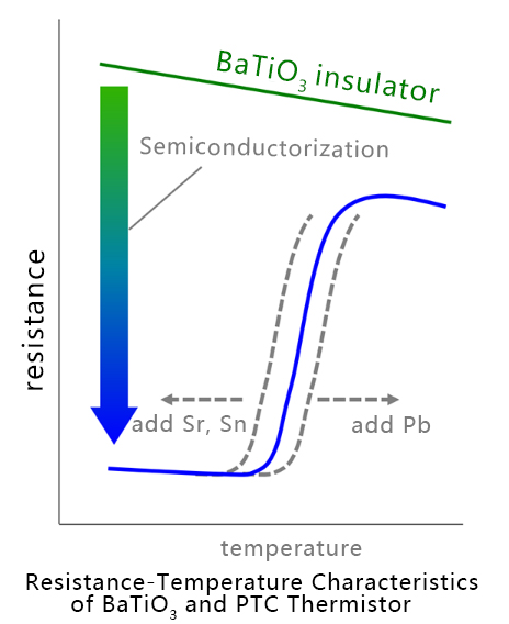
Barium titanate (BaTiO3), discovered by Japan, the United States, and the Soviet Union in the early 1940s, generally has a resistivity greater than 1010Ω·cm at room temperature. In 1952, Haayman et al. of Philips (Netherlands) found that when a small amount of rare earth elements (Y, Bi, Sb, etc.) were added, its resistivity became 10~106Ω·cm, and the temperature characteristics of the material corresponded to the Curie point. However, they did not publish any literature at the time, but only applied for a patent, so it was not known to the public until around 1954. In 1961, PTC thermistors were first mass-produced by Murata Manufacturing and obtained the registered trademark of POSISTOR. Around 1963, European, American, and Japanese companies began to industrialize PTC thermistors, which were applied in temperature compensation, water level detection, motor overheating prevention, automatic temperature control heaters, color TV demagnetization circuits, and other fields.

PTC Thermistor Selection Parameters
Understanding key parameters is essential for selecting the right PTC thermistor for your application. Here are the five critical factors to consider.
1. Maximum operating voltage
PTC thermistors are connected in series in the circuit. During normal operation, only a small portion of the voltage remains on the PTC thermistor. When the PTC thermistor starts in a high-resistance state, it must withstand almost the entire power supply voltage. Therefore, when selecting a PTC thermistor, a sufficiently high maximum operating voltage must be selected, and possible fluctuations in the power supply voltage must also be considered.
2. Non-operating current and operating current
In order to obtain reliable switching function, the operating current must be at least twice the non-operating current. Since the ambient temperature has a great influence on the non-operating current and the operating current (see the figure below), the worst case should be taken into account. The non-operating current should be selected at the highest allowable ambient temperature, and for the operating current, the value used at a lower ambient temperature should be selected.
3. Maximum current allowed at maximum operating voltage
When the PTC thermistor performs the protection function, check whether there are conditions in the circuit that produce a current exceeding the maximum allowable current, which generally refers to the possibility of a short circuit. The maximum current value has been given in the specification. If it is used beyond this value, the PTC thermistor may be damaged or fail prematurely.
4. Switching temperature (Curie temperature)
We can provide overcurrent protection components with Curie temperatures of 80℃, 100℃, 120℃, 140°C, etc. On the one hand, the non-operating current depends on the Curie temperature and the diameter of the PTC thermistor chip. In order to reduce costs, high Curie temperature and small size components should be selected; on the other hand, it must be considered that the PTC thermistor selected in this way will have a higher surface temperature, whether it will cause undesirable side effects in the circuit. In general, the Curie temperature should exceed the maximum ambient temperature of use by 20~40°C.
5. Influence of the use environment
When contacting with chemical reagents or using potting materials or fillers, special care must be taken to prevent the reduction of barium titanate ceramics, which may lead to a decrease in the effect of the PTC thermistor, and changes in thermal conductivity caused by potting, which may cause local overheating and damage to the PTC thermistor.
The Example of Selecting PTC Thermistor for Power Transformer
It is known that the primary voltage of the power transformer is 220V, the secondary voltage is 16V, the secondary current is 1.5A, the primary current is about 350mA when the secondary is abnormal, and it should enter the protection state within 10 minutes. The working environment temperature of the transformer is -10 ~ 40℃, and the temperature rise is 15~~20℃ during normal operation. The PTC thermistor is installed close to the transformer. Please select a PTC thermistor for primary protection.
1. Determine the maximum working voltage
It is known that the working voltage of the transformer is 220V. Considering the power supply fluctuation factor, the maximum working voltage should reach 220V×(1+20%) =264V<br/>The maximum working voltage of the PTC thermistor is 265V.
2. Determine the non-operating current
After calculation and actual measurement, the primary current of the transformer is 125mA when it is working normally. Considering that the ambient temperature of the installation location of the PTC thermistor is as high as 60℃, it can be determined that the non-operating current should be 130~140mA at 60℃.
3. Determine the operating current
Considering that the ambient temperature of the installation location of the PTC thermistor can be as low as -10℃ or 25℃, it can be determined that the operating current should be 340~350mA at -10℃ or 25℃, and the operating time is about 5 minutes.
4. Determine the rated zero power resistance R25
The PTC thermistor is connected in series in the primary, and the voltage drop generated should be as small as possible. The heating power of the PTC thermistor itself should also be as small as possible. Generally, the voltage drop of the PTC thermistor should be less than 1% of the total power supply. R25 is calculated:<br/>220V x 1%÷0.125A=17.6Ω
5. Determine the maximum current
According to actual measurement, when the secondary of the transformer is short-circuited, the primary current can reach 500mA. If a larger current passes when a partial short circuit occurs in the primary coil, the maximum current of the PTC thermistor is determined to be above 1A.
6. Determine the Curie temperature and dimensions
Considering that the ambient temperature of the installation location of the PTC thermistor can reach up to 60°C, the Curie temperature is selected by adding 40°C on this basis, and the Curie temperature is 100°C. However, considering the low cost and the fact that the PTC thermistor is not installed in the transformer coil, its higher surface temperature will not have an adverse effect on the transformer, so the Curie temperature can be selected as 120°C, so that the diameter of the PTC thermistor can be reduced by one level and the cost can be reduced.
7. Determine the model of the PTC thermistor
According to the above requirements, refer to our company's specification table and select MZ11-10P15RH265<br/>That is: maximum operating voltage 265V, rated zero-power resistance value 15Q±25%, non-operating current 140mA, operating current 350 mA, maximum current 1.2A, Curie temperature 120°C, and maximum size 11.0mm.

PTC Thermistor Core Advantages
PTC thermistors offer unique advantages that make them ideal for various protection and control applications in electronic circuits.
Self-protection function
When the temperature exceeds the threshold, the resistance of the thermistor increases sharply, automatically limiting the current. Examples include motor overcurrent protection and lithium battery protection.
No external control required
The passive nature of the thermistor responds directly to temperature changes, which simplifies circuit design and reduces system complexity.
Long life
The absence of mechanical contacts prevents aging, making them a durable alternative to traditional fuses with extended operational lifespan.
Customizability
The ability to adjust the Curie point through material modification, with ceramic PTCs capable of reaching temperatures between 20-300°C for various applications.
When the circuit is in a normal state, the current passing through the overcurrent protection PTC thermistor is less than the rated current, and the overcurrent protection PTC thermistor is in a normal state with a very small resistance value, which will not affect the normal operation of the protected circuit. When a circuit fails and the current greatly exceeds the rated current, the overcurrent protection PTC thermistor suddenly heats up and becomes a high-resistance state, putting the circuit in a relatively "disconnected" state, thereby protecting the circuit from damage. When the fault is eliminated, the overcurrent protection PTC thermistor also automatically returns to a low-resistance state, and the circuit resumes normal operation.

When the circuit is in a normal state, the current passing through the overcurrent protection PTC thermistor is less than the rated current, and the overcurrent protection PTC thermistor is in a normal state with a very small resistance value, which will not affect the normal operation of the protected circuit. When a circuit fails and the current greatly exceeds the rated current, the overcurrent protection PTC thermistor suddenly heats up and becomes a high-resistance state, putting the circuit in a relatively "disconnected" state, thereby protecting the circuit from damage. When the fault is eliminated, the overcurrent protection PTC thermistor also automatically returns to a low-resistance state, and the circuit resumes normal operation.
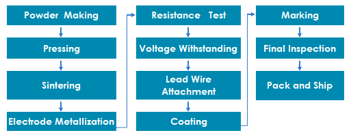
PTC Thermistor Manufacturing Process
The manufacture of PTC thermistors begins with a mixture of barium carbonate, titanium oxide and other materials that produce the desired electrical and thermal characteristics, which are ground, mixed and compressed into discs or rectangles and then sintered, preferably at a temperature below 1400°C. After that, they are carefully connected together, equipped with connecting elements depending on the model, and finally coated or encapsulated.


PTC Thermistor Typical Applications
Overcurrent protection: home appliances (hair dryers, coffee machines), automotive electronics. Temperature sensing and compensation: industrial equipment temperature control system. Self-regulating heating: constant temperature heater (the resistance of ceramic PTC is stable near the Curie point). Electronic circuit protection: USB current limiting, PCB over-temperature protection.