
Quick Answer: What Does the WMZ12A Datasheet Tell Engineers?
A WMZ12A datasheet should help engineers verify a thermistor's resistance at 25°C (R25), resistance tolerance, switching behavior, voltage and current limits, physical dimensions, and recovery characteristics. Tianrui publishes general WMZ12A series specifications, but these do not establish the ratings of every individual part number. For OEM replacement approval, obtain the exact manufacturer specification and verify its behavior in the intended protection circuit.
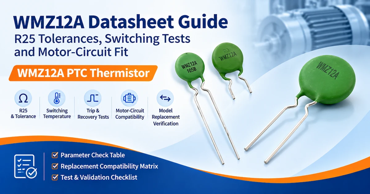
Key Takeaways
-
The publicly listed WMZ12A series covers R25 values of 10–2200Ω, with a stated ±30% tolerance.
-
Tianrui also lists a Curie temperature range of 50–120°C and diameters of 4.5–24mm.
-
These are series-level ranges, not the complete specifications of one particular WMZ12A component.
-
R25 tolerance, switching temperature, hold current, trip current, and maximum operating voltage describe different characteristics.
-
A PTC thermistor that enters a high-resistance condition does not necessarily create an open circuit.
-
Resettable overcurrent protection and motor-winding temperature monitoring require different circuit evaluations.
-
A substitute should not be approved based on matching R25 and diameter alone.
-
OEM buyers should request the full model code, controlled datasheet, applicable test conditions, and representative samples before production approval.
What Is the WMZ12A PTC Thermistor Used For?
The WMZ12A is a ceramic positive temperature coefficient thermistor series published by Dongguan Tianrui Electronics Co., Ltd.
Its resistance increases sharply as the ceramic temperature reaches a characteristic transition region.
In an appropriate circuit, this behavior can be used to restrict current after an abnormal electrical or thermal condition.
Tianrui's WMZ12A Series PTC Thermistor product page identifies applications including:
-
Electronic ballasts.
-
Compact fluorescent lamp circuits.
-
Power adapters.
-
Chargers.
-
Other electronic overcurrent-protection circuits.
The product description also discusses motor-related protection applications.
However, motor protection can refer to different electrical functions.
Current-limiting protection
A series-connected PTC thermistor may carry normal operating current and develop additional self-heating during an overload.
As resistance increases, the device can limit the current flowing through the protected circuit.
Its suitability depends on voltage, normal current, fault current, thermal conditions, and the required protective response.
Motor winding temperature monitoring
A temperature-sensing PTC is typically positioned near a motor winding and connected to a monitoring or protection circuit.
It responds primarily to the winding temperature, and a controller or relay interprets the resulting resistance change.
The sensor does not necessarily carry the motor's operating current.
These two arrangements must not be treated as interchangeable.
A WMZ12A component advertised for overcurrent protection should not automatically be approved as an embedded motor-winding sensor.
The intended circuit function, installation method, insulation requirements, and complete part number must be confirmed.
For a detailed introduction to temperature-sensing applications, see Tianrui's existing PTC Thermistor for Motor Protection Guide.
This article focuses instead on WMZ12A specification interpretation and replacement verification.
How to Read WMZ12A R25 Resistance and Tolerance
R25 is one of the first parameters engineers examine when comparing two thermistors.
It represents the device's specified resistance at 25°C under defined low-self-heating measurement conditions.
However, R25 alone cannot establish whether a thermistor will provide the same protection response in a circuit.
What does Tianrui actually publish?
The official WMZ12A PTC Thermistor Specifications provide the following series-level information, including R25 resistance, tolerance, Curie temperature, and physical dimensions.
Table 1. WMZ12A Published Specifications and Verification Requirements
| Parameter | Tianrui's Published Series Information | Engineering Interpretation | Additional Information Required |
|---|---|---|---|
| Product series | WMZ12A | Ceramic PTC thermistor family | Full ordering part number |
| R25 resistance | 10–2200Ω | Available resistance range across the series | Nominal R25 for the selected model |
| R25 tolerance | ±30% stated | Resistance variation relative to the nominal value | Part-specific acceptance limits and measurement conditions |
| Curie temperature | 50–120°C | Series-level temperature range | Specific nominal value and tolerance |
| Diameter | 4.5–24mm | General physical size range | Exact dimensions and mechanical drawing |
| Product color | Green | Published visual characteristic | Actual coating and package specification |
| Primary listed applications | Ballast, CFL, adapter, charger protection | Intended circuit-protection direction | Application-specific electrical qualification |
| Maximum voltage | Not established in the public summary | Critical operating limit | Manufacturer-confirmed rating |
| Hold/non-trip current | Not established in the public summary | Relevant to normal operation | Rating and temperature conditions |
| Trip current | Not established in the public summary | Relevant to fault response | Rating and test definition |
| Trip time | No complete test condition provided | Depends on current and thermal environment | Time-current data |
| Recovery behavior | Described generally | Must be characterized in the actual circuit | Recovery conditions and acceptance limits |
Important distinction:
The published R25 range and diameter range do not demonstrate which resistance value corresponds to which diameter.
An OEM should not construct a fictional specification by combining arbitrary values from separate series ranges.
How is R25 tolerance calculated?
For a hypothetical thermistor with:
-
Nominal R25: 100Ω.
-
Resistance tolerance: ±30%.
The theoretical resistance limits would be:
Minimum R25 = 100 × 0.70 = 70Ω
Maximum R25 = 100 × 1.30 = 130Ω
Therefore, the illustrative acceptance range is 70–130Ω, assuming the measurement method matches the specified conditions.
This calculation demonstrates tolerance interpretation only.
It does not represent a confirmed Tianrui WMZ12A model with a nominal resistance of 100Ω.
Why can two thermistors with matching R25 behave differently?
Two PTC thermistors may have similar resistance at 25°C but different:
-
Ceramic resistance-temperature curves.
-
Switching-temperature characteristics.
-
Thermal mass.
-
Package geometry.
-
Current-handling capability.
-
Heat dissipation.
-
Recovery behavior.
For example, a larger ceramic disc may heat differently from a smaller disc under otherwise similar electrical conditions.
Likewise, two components with equal cold resistance may require different fault currents to reach a high-resistance condition.
How should R25 be measured?
The measurement procedure should minimize self-heating and follow the specified manufacturer method.
Record:
-
Stabilized ambient temperature.
-
Measurement equipment.
-
Applied measurement voltage or current.
-
Measurement duration.
-
Component identification.
-
Measured resistance.
-
Acceptance criteria.
A high test current can heat the PTC element and change its resistance during measurement.
This can make the reading unsuitable for verification against the manufacturer's defined R25 specification.
Recommended incoming inspection record
| Sample ID | Full Model Code | Nominal R25 | Published Tolerance | Measured R25 | Result |
|---|---|---|---|---|---|
| Sample A | To be confirmed | Datasheet value | Datasheet value | Measured value | Pass/Fail |
| Sample B | To be confirmed | Datasheet value | Datasheet value | Measured value | Pass/Fail |
| Sample C | To be confirmed | Datasheet value | Datasheet value | Measured value | Pass/Fail |
This worksheet is more useful for production quality control than assuming that every WMZ12A device should have the same resistance.
What Does WMZ12A Switching Temperature Actually Mean?
A PTC thermistor's switching behavior is associated with a significant resistance increase as its temperature rises.
However, several temperature-related terms must be distinguished.
Curie temperature
The Curie temperature is associated with the ceramic material's transition behavior.
Tianrui lists a WMZ12A series Curie temperature range of 50–120°C.
This range does not specify the exact switching point of every device.
Resistance-temperature transition
The resistance-temperature characteristic describes how electrical resistance changes with ceramic temperature.
For engineering verification, the manufacturer should provide the applicable resistance-temperature curve or defined resistance limits at specified temperatures.
Circuit trip temperature
The point at which the protection circuit responds depends on the actual application.
For a current-limiting PTC, device temperature results from a combination of self-heating, ambient conditions, electrical current, and heat dissipation.
For a temperature-monitoring circuit, the response also depends on sensor placement and the controller's resistance threshold.
Therefore:
Curie temperature ≠ guaranteed equipment trip temperature.
Why the distinction matters
Suppose an OEM selects a thermistor solely because the product family includes a 100°C Curie temperature option.
That does not prove that the equipment will disconnect or limit current at precisely 100°C.
The full thermistor characteristic and protection-system response must be evaluated.
Switching-temperature verification checklist
| Parameter | Verification Question |
|---|---|
| Nominal switching temperature | What is the exact model specification? |
| Switching tolerance | What variation is permitted? |
| R–T curve | What resistance values occur across the relevant range? |
| Electrical load | Is the component self-heated during operation? |
| Ambient temperature | How does ambient temperature affect response? |
| Controller threshold | What condition activates protection? |
| Temperature measurement | Where is the test temperature measured? |
| Thermal coupling | How is heat transferred from the protected component? |
A model should not be approved without understanding how these variables interact.
How Should Engineers Verify Trip and Recovery Behavior?
Trip and recovery testing determines whether the thermistor produces the intended protective response under the specified conditions.
The manufacturer's complete part-specific datasheet should define the applicable electrical limits and characteristic measurements.
Step 1: Establish the normal operating condition
Record the intended supply voltage, operating current, ambient temperature, component mounting, and thermal environment.
Verify that the thermistor does not produce unacceptable current limiting during permitted normal operation.
Step 2: Define the fault condition
The fault scenario should reflect the actual equipment.
Examples might include a sustained overload, restricted cooling, or another relevant condition.
The laboratory test must remain within an appropriately controlled and protected setup.
Step 3: Measure current and voltage versus time
During a controlled test, record:
-
Thermistor terminal voltage.
-
Circuit current.
-
Starting temperature.
-
Ambient temperature.
-
Time-dependent electrical behavior.
-
Temperature where relevant.
-
Fault-clearing behavior.
Step 4: Determine the trip criterion
A PTC does not necessarily switch at one universally defined current.
The applicable trip criterion must be established from the manufacturer's specification and the OEM's circuit requirements.
For example, the test may evaluate whether current decreases below a defined application threshold within an agreed time.
Such thresholds should not be invented.
Step 5: Evaluate residual current
A current-limiting PTC enters a high-resistance state.
This does not necessarily mean that current becomes zero or that the circuit is physically isolated.
Residual current may remain and must be considered in the protection design.
Step 6: Verify recovery behavior
Recovery generally requires the thermistor to cool sufficiently.
Depending on the circuit, continued electrical power can maintain self-heating and delay recovery.
The test should establish the conditions under which the device returns toward its initial resistance state.
Step 7: Evaluate repeatability
For appropriate designs, repeated operating and fault cycles may be required.
Record whether the component's relevant electrical characteristics remain within the approved limits.
Table 2. WMZ12A Trip-and-Recovery Test Worksheet
| Test Stage | Required Measurement | Acceptance Criterion |
|---|---|---|
| Initial condition | R25, ambient temperature | Model-specific specification |
| Normal operation | Current, voltage, component temperature | No unintended protection response |
| Defined overload | Current and voltage versus time | Approved fault-response limits |
| High-resistance state | Residual current, temperature | Equipment protection requirement |
| Fault removal | Supply and current conditions | Defined recovery procedure |
| Cooling | Resistance versus time | Model-specific recovery limits |
| Re-energization | Current and device response | Approved restart behavior |
| Repeated cycling | R25, trip behavior, physical condition | Approved durability criteria |
The table is a proposed OEM validation template, not a published Tianrui WMZ12A test report.
Why are general response-time claims insufficient?
A statement such as "fast response" does not provide a complete engineering acceptance criterion.
Trip time depends on electrical current, initial temperature, mounting, environmental conditions, and the definition of trip.
A component may behave very differently under two fault conditions.
The OEM should request measured time-current data or a model-specific test procedure rather than relying on an unspecified response-time claim.
WMZ12A for Motor Protection: Is Every Configuration Suitable?
No.
A PTC thermistor used for motor protection must be matched to the intended protection architecture.
Two common approaches are electrical current limiting and winding-temperature monitoring.
Table 3. Motor-Circuit Protection Comparison
| Engineering Factor | Series Current-Limiting PTC | Motor Winding Temperature-Sensing PTC |
|---|---|---|
| Primary function | Restrict current during a defined fault | Detect excessive winding temperature |
| Connection | In series with the protected circuit | Connected to monitoring or protection electronics |
| Normal electrical behavior | Carries circuit current | Typically operates in a sensing circuit |
| Main thermal stimulus | Self-heating and ambient temperature | Motor winding temperature |
| Critical ratings | Voltage, normal current, trip current, fault behavior | Response temperature, R–T limits, relay compatibility |
| Installation concern | Electrical and thermal loading | Thermal contact and winding insulation |
| Protective output | Increased resistance limits current | Controller or relay initiates protective action |
| Main qualification | Circuit fault testing | Winding temperature and protection-system testing |
Can WMZ12A be used as a motor current limiter?
A specific WMZ12A configuration may be evaluated for motor-related overcurrent protection when its electrical ratings and fault characteristics are compatible with the motor circuit.
However, the supplier must confirm the exact model's suitability.
The motor's normal starting current and operating conditions should be included in the evaluation.
A current-limiting PTC that trips during normal startup would be unsuitable.
Can WMZ12A be installed inside motor windings?
The WMZ12A product description mentions motor-related applications, but the public series summary does not establish a complete winding-sensor specification for a particular WMZ12A part.
Before approving an embedded application, the OEM should verify the sensor's intended function, temperature rating, construction, insulation, dimensions, and compatibility with the protection circuit.
Tianrui separately publishes Motor Protection PTC Thermistors with response-temperature and resistance information specifically related to winding-temperature monitoring.
These products should be considered separately from current-limiting thermistors.
Relevant motor protection standard
IEC 60034-11:2020 — Rotating Electrical Machines: Thermal Protection addresses thermal protectors and detectors incorporated into windings or installed at suitable locations within its defined motor scope.
For qualifying motor winding protection, it offers a relevant reference for the complete thermal-protection system.
It does not prove that every WMZ12A component is suitable for winding installation or has received IEC certification.
Motor compatibility questions
Before approving the component, answer:
-
Is the intended function current limiting or temperature sensing?
-
Does the thermistor carry motor current?
-
What current occurs during normal starting?
-
What abnormal current or winding temperature must trigger protection?
-
What maximum voltage and fault conditions apply?
-
What protective controller or relay is used?
-
Is the package suitable for the installation environment?
-
What happens when the fault clears?
-
Is automatic restart permitted?
-
What final equipment testing is required?
These questions prevent the common mistake of treating all motor-related PTC thermistors as electrically interchangeable.
How to Compare WMZ12A with an Existing Protection Thermistor
Replacing a thermistor requires more than matching its physical diameter.
The existing device and candidate WMZ12A part must be compared using the same operating and test conditions.
Step 1: Identify the original component
Collect the complete original part number and latest applicable datasheet.
Do not rely on a shortened marking or product-family designation where it does not identify the exact electrical configuration.
Step 2: Define the circuit function
Determine whether the original part is used for:
-
Series overcurrent limiting.
-
Overtemperature sensing.
-
Motor-starting control.
-
Another specific PTC function.
A candidate designed for one function should not be assumed suitable for another.
Step 3: Compare the complete electrical characteristics
The important parameters depend on the application.
For an overcurrent limiter, they may include R25, hold current, trip current, maximum voltage, permissible fault current, and recovery behavior.
For a sensing component, resistance-temperature limits and controller thresholds may be more important.
Step 4: Compare thermal and mechanical construction
Even if the electrical characteristics are compatible, the replacement must fit the assembly.
Review the diameter, thickness, lead spacing, lead shape, coating, and mounting environment.
Table 4. Original vs. WMZ12A Replacement Compatibility Matrix
| Parameter | Original Component | Candidate WMZ12A | Verification Status |
|---|---|---|---|
| Full part number | Original datasheet | Tianrui-confirmed model | Open / Pass / Fail |
| Circuit function | Defined application | Confirmed function | Open / Pass / Fail |
| Nominal R25 | Exact value | Exact value | Open / Pass / Fail |
| R25 tolerance | Defined limit | Defined limit | Open / Pass / Fail |
| R–T characteristic | Original curve | Candidate curve | Open / Pass / Fail |
| Curie/switching temperature | Exact specification | Exact specification | Open / Pass / Fail |
| Maximum operating voltage | Rated value | Rated value | Open / Pass / Fail |
| Normal/hold current | Defined condition | Defined condition | Open / Pass / Fail |
| Trip current | Defined condition | Defined condition | Open / Pass / Fail |
| Trip time | Required test conditions | Measured or specified | Open / Pass / Fail |
| Fault-current capability | Required limit | Manufacturer-confirmed limit | Open / Pass / Fail |
| Residual current | Application requirement | Candidate behavior | Open / Pass / Fail |
| Recovery behavior | Original requirement | Candidate behavior | Open / Pass / Fail |
| Diameter and thickness | Mechanical drawing | Candidate drawing | Open / Pass / Fail |
| Lead configuration | Existing PCB or assembly | Candidate construction | Open / Pass / Fail |
| Insulation/environment | Equipment requirements | Verified suitability | Open / Pass / Fail |
This matrix is intended to be completed using real manufacturer documents and measured results.
No candidate should be marked as a direct replacement while critical compatibility fields remain unverified.
Step 5: Determine whether the substitution changes equipment protection
A new thermistor may affect startup behavior, fault response, residual current, and recovery.
The OEM should evaluate whether other protective components or circuit functions are affected.
Step 6: Approve the replacement through engineering change control
Once qualification is complete, update:
-
Approved component list.
-
BOM and drawings.
-
Test requirements.
-
Incoming inspection criteria.
-
Assembly instructions.
-
Revision records.
If the replacement is not technically equivalent, it should be treated as a design change rather than a direct substitution.
What Testing Is Required Before Replacing a WMZ12A Component?
A qualified replacement must meet the intended electrical, mechanical, and thermal requirements of the equipment.
The validation plan should reflect the circuit's actual function.
Table 5. WMZ12A Replacement Qualification Matrix
| Test Category | Main Measurement | Engineering Objective |
|---|---|---|
| Incoming R25 | Resistance at specified temperature | Verify initial electrical characteristics |
| Temperature-resistance response | Resistance at defined temperatures | Assess switching behavior |
| Normal operating current | Current and PTC temperature | Prevent unwanted activation |
| Startup or transient load | Current and response | Verify acceptable normal operation |
| Defined fault condition | Current and voltage versus time | Assess protection performance |
| Residual current | Current in high-resistance state | Verify fault-energy limitation |
| Recovery | Resistance and temperature after fault | Confirm suitable reset behavior |
| Repeated fault cycles | Characteristic changes | Evaluate repeatability |
| Voltage tolerance | Relevant electrical behavior | Assess supply compatibility |
| Dimensional inspection | Diameter, thickness, lead spacing | Verify installation |
| Environmental exposure | Electrical and mechanical condition | Evaluate intended environment |
| Final circuit test | Complete protective response | Confirm system compatibility |
The supplier and OEM should agree on the required test conditions and acceptance criteria.
Component-level reference
IEC 60738-1:2022 — Thermistors: Directly Heated Positive Temperature Coefficient defines terminology and test methods for directly heated PTC thermistors within its scope.
This makes it relevant when creating a consistent component qualification plan.
However, the OEM must still specify the circuit-level requirements.
The existence of the standard does not establish compliance or certification for a particular Tianrui model.
How many samples should be tested?
There is no universally applicable sample quantity that can be assigned without knowing the project.
Sample quantity depends on factors such as:
-
Application risk.
-
Test purpose.
-
Production volume.
-
Device variation.
-
Qualification requirements.
-
Whether testing is destructive.
-
OEM quality procedures.
The engineering team should define the sampling plan rather than invent a fixed quantity.
What should be included in the final test report?
A complete record should identify:
-
Original and candidate part numbers.
-
Supplier and component revision.
-
Test method.
-
Test equipment.
-
Applied electrical conditions.
-
Ambient and component temperatures.
-
Mounting configuration.
-
Measured results.
-
Acceptance criteria.
-
Pass/fail decisions.
-
Engineering approval.
How should engineers handle a failed comparison?
A failed test does not automatically mean the candidate thermistor is defective.
The failure may indicate that the candidate is unsuitable for the intended application.
For example, a component that activates too early under normal startup conditions may be functioning correctly according to its own specification but still fail the OEM's requirements.
This distinction is important when assessing replacement compatibility.
WMZ12A OEM Sourcing and Model Verification Checklist
For OEM buyers, the most important step is identifying the exact thermistor configuration before requesting a production quotation.
A generic WMZ12A series designation is not sufficient to establish every critical electrical parameter.
Required documentation
| Document or Information | Purpose |
|---|---|
| Complete WMZ12A part number | Identify the exact configuration |
| Manufacturer-issued datasheet | Establish rated characteristics |
| Mechanical drawing | Confirm installation and PCB compatibility |
| Resistance-temperature data | Verify thermal response |
| Current and voltage ratings | Establish electrical limits |
| Trip and recovery data | Evaluate protective behavior |
| Material and coating information | Review environmental suitability |
| Sample test requirements | Establish qualification expectations |
| Applicable inspection criteria | Support incoming quality control |
| Estimated order quantity | Support commercial evaluation |
What information is currently available from Tianrui?
Tianrui's public WMZ12A page confirms the product family and provides broad specification ranges.
It also describes overcurrent protection and related applications.
However, the publicly verified information does not establish a complete downloadable manufacturer datasheet for a particular WMZ12A variant.
Buyers searching for a WMZ12A datasheet should therefore request the exact manufacturer-issued file.
A third-party datasheet for another supplier's WMZ12A series should not automatically be presented as Tianrui's official specification.
What should engineers send for replacement evaluation?
A useful technical inquiry should include:
-
The original thermistor part number.
-
The original manufacturer's datasheet.
-
Application circuit schematic or relevant diagram.
-
Normal operating voltage and current.
-
Startup or transient current conditions.
-
Fault-current and protection requirements.
-
Required temperature behavior.
-
Mechanical dimensions and lead configuration.
-
Environmental conditions.
-
Sample and projected production quantities.
Example Technical Inquiry
Subject: WMZ12A PTC Thermistor Datasheet and OEM Replacement Verification
We are evaluating the WMZ12A PTC thermistor series for an electronic protection circuit.
Our project requires verification of R25 resistance, switching characteristics, current ratings, recovery behavior, and mechanical compatibility.
We can provide the existing thermistor part number, application schematic, normal operating current, fault conditions, and purchasing forecast.
Please advise:
-
Which Tianrui WMZ12A model is suitable for evaluation.
-
Whether a manufacturer-issued datasheet is available for the exact model.
-
What R25 values and tolerances apply.
-
What maximum voltage, non-trip current, and trip-current specifications apply.
-
What trip and recovery test information can be provided.
-
Whether the candidate is suitable for the intended motor or electronic protection circuit.
-
What engineering samples and commercial conditions are available.
We would like to complete compatibility testing before approving any substitution.
For technical assistance, contact Tianrui Electronics with the original part number and available application information.
Engineering and procurement considerations
Dongguan Tianrui Electronics Co., Ltd. publishes WMZ12A thermistors alongside other PTC protection components.
For a complete overview of related device families, see its PTC Thermistor products.
A suitable supplier proposal should identify the exact model, required engineering verification, and commercial terms.
MOQ, lead time, and customized specifications should be confirmed for the specific part rather than assumed from the product family's general description.
Frequently Asked Questions About WMZ12A Datasheets
1. What is a WMZ12A datasheet?
A WMZ12A datasheet is a technical specification document for a defined thermistor model.
It should describe the relevant resistance, temperature, voltage, current, physical, and test characteristics needed to evaluate the component.
A general series description is useful for initial research but may not contain enough information to approve a specific replacement.
2. What is the R25 resistance range of Tianrui's WMZ12A series?
Tianrui's public product information states an R25 series range of 10–2200Ω with a ±30% tolerance notation.
This does not mean that every model has the same nominal resistance.
The exact value must be confirmed using the complete model specification.
3. What does ±30% R25 tolerance mean?
It means the specified allowable resistance deviation is 30% above or below the relevant nominal value, assuming that is the defined tolerance for the selected model.
For example, a hypothetical 100Ω device with ±30% tolerance would have limits of 70–130Ω under the specified measurement conditions.
This is an illustration, not a confirmed WMZ12A model rating.
4. What is the WMZ12A switching temperature?
Tianrui lists a Curie temperature range of 50–120°C for the WMZ12A series.
The exact nominal temperature, tolerance, and switching behavior of an individual configuration require its corresponding specification.
The Curie temperature should not be interpreted as a guaranteed circuit trip point.
5. Does a WMZ12A thermistor completely disconnect a circuit?
Not necessarily.
A current-limiting PTC increases resistance and reduces current under appropriate conditions.
Residual current may remain.
The protection circuit must be designed to satisfy the applicable electrical and safety requirements.
6. Can WMZ12A be used for motor protection?
A suitable configuration may be considered for a defined motor-related protection function.
However, series current limiting and motor-winding temperature monitoring are different applications.
The exact component must be evaluated for the intended function, voltage, current, thermal conditions, and installation.
7. Can WMZ12A replace another PTC thermistor with the same R25?
Not automatically.
Matching R25 does not establish equivalent switching temperature, hold current, trip current, voltage capability, recovery, or physical compatibility.
Replacement approval should use a complete parameter comparison and circuit-level verification.
8. How long does a WMZ12A thermistor take to trip?
There is no single verified trip-time value for every WMZ12A configuration in Tianrui's public series summary.
Trip behavior depends on the part, current, voltage, ambient temperature, and thermal conditions.
Engineers should request model-specific time-current data or conduct controlled tests.
9. Does a WMZ12A thermistor automatically reset after a fault?
A suitable resettable PTC can return toward its lower-resistance condition after the relevant fault and self-heating have been removed and the device cools.
The actual recovery conditions and time depend on the selected component and circuit.
Component recovery does not automatically justify restarting the protected equipment.
10. Where can OEM buyers obtain the correct WMZ12A datasheet?
The first step is to identify the complete WMZ12A part number.
Buyers should then request the manufacturer-issued specification from Tianrui and verify the revision, electrical ratings, temperature characteristics, and dimensions.
For replacement projects, provide the original component's datasheet and circuit requirements to support compatibility evaluation.
Conclusion
A reliable WMZ12A datasheet should provide enough information to evaluate the exact thermistor configuration, not merely identify a broad product family.
For electronics engineers and OEM purchasing teams, the most important requirements are:
-
R25 verification: Confirm the nominal resistance, tolerance, and measurement conditions.
-
Switching characteristics: Understand the difference between Curie temperature and actual protection behavior.
-
Electrical ratings: Establish the permitted voltage, normal current, trip current, and fault conditions.
-
Trip and recovery testing: Measure the protection response under defined application conditions.
-
Motor-circuit compatibility: Distinguish current-limiting PTC devices from winding-temperature sensing thermistors.
-
Replacement validation: Compare electrical, thermal, and mechanical characteristics against the original component.
-
Production approval: Use controlled specifications, engineering samples, and inspection criteria.
Tianrui's published WMZ12A PTC thermistor series includes a broad selection of resistance, temperature, and diameter ranges.
However, series-level specifications alone are not sufficient to approve a particular component for an electronic circuit or motor protection application.
The correct selection depends on verified part-specific characteristics and complete system compatibility.
Need to verify a WMZ12A model or evaluate a replacement PTC thermistor?
Review the Tianrui WMZ12A Series PTC Thermistor and contact Tianrui Electronics to request the applicable technical specification, discuss the protection circuit, and arrange engineering sample evaluation.
When submitting an inquiry, include the original part number, required R25, relevant voltage and current conditions, temperature requirements, physical dimensions, and planned purchasing quantity.
Email:
Phone:
+86 135 3277 2961
A confirmed model-specific datasheet, appropriate circuit testing, and controlled replacement approval process provide a more reliable foundation for OEM component selection and long-term procurement.