A Motor Protection Thermistor is a temperature-sensitive component installed in or near a motor winding to detect excessive heat before it causes unacceptable damage. For three-phase motor OEMs, the correct selection depends on the rated response temperature (Tk), resistance characteristics, sensor configuration, thermal installation, and compatibility with the motor protection relay.
A suitable thermistor does not independently disconnect the motor's power supply. Instead, its resistance increases sharply when the monitored winding reaches a defined temperature. A compatible evaluation relay detects the resistance change and initiates the required protective action through the motor control system.
This distinction matters for manufacturers of industrial motors, compressors, pumps, ventilation equipment, and automated machinery. A sensor with the wrong switching temperature or resistance characteristics may cause nuisance shutdowns, delayed protection, or unreliable operation.
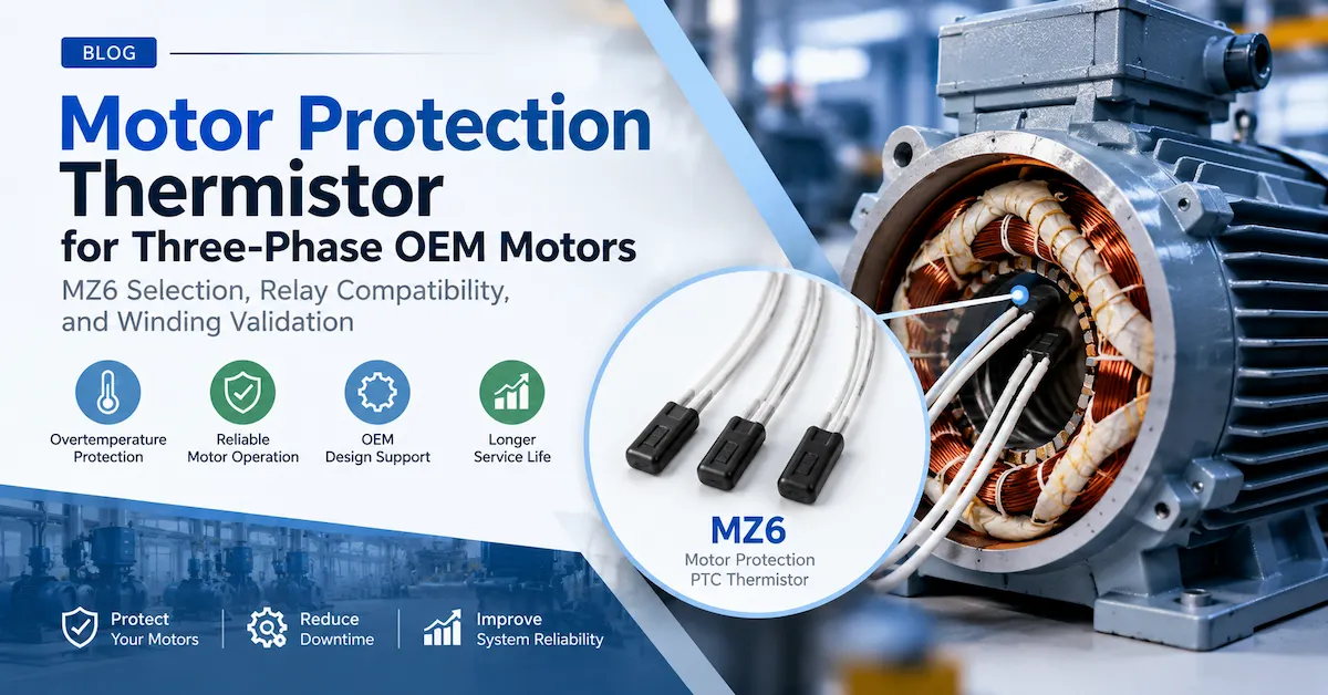
This article focuses on practical OEM engineering decisions, including the Tianrui MZ6 motor protection thermistor series, three-sensor configurations, winding installation, electrical verification, and procurement requirements.
1. What Is a Motor Protection Thermistor?
A motor protection thermistor is a thermally sensitive resistor used to monitor motor temperature and support an overtemperature protection function.
In a typical PTC-based motor protection system, the sensor is embedded in the stator winding or placed in another thermally relevant position. It is connected to a separate protection relay or compatible electronic control circuit.
PTC stands for Positive Temperature Coefficient. In a switching-type ceramic PTC thermistor, resistance rises sharply as the component approaches its specified response-temperature region.
The protection process follows a straightforward sequence:
Winding temperature rises → PTC resistance increases → Relay detects the change → Motor control system initiates shutdown or alarm.
The complete protective action depends on the relay, contactor or drive interface, system wiring, and the selected restart behavior.
Why direct winding temperature detection matters
Motor overheating does not always result from excessive current alone.
Consider a motor operating with restricted cooling airflow. Its current may remain near the expected operating range while internal winding temperature rises because heat cannot escape efficiently.
A conventional current-sensitive overload device may not directly detect that temperature increase.
A properly installed winding thermistor responds to the local temperature rather than attempting to infer all thermal conditions from motor current.
Other situations that can contribute to excessive winding temperature include:
-
Mechanical overload or blocked rotation.
-
Repeated starting with insufficient cooling intervals.
-
High ambient temperature.
-
Cooling fan failure or blocked ventilation passages.
-
Supply voltage imbalance.
-
Abnormal operating duty.
-
Reduced cooling at low rotational speed.
-
Process conditions that increase the mechanical load.
However, winding PTC sensors do not replace every other protection function. Short-circuit protection, ground-fault protection, safe isolation, and other safeguards must still be considered according to the complete motor installation.
What a motor protection thermistor cannot do
A common purchasing mistake is assuming that the thermistor itself is an automatic power-disconnection device.
Most motor winding PTC thermistors operate within a low-energy monitoring circuit. Their purpose is to provide a temperature-dependent resistance signal.
The protection relay interprets this signal and controls the associated protective equipment.
This means that a suitable thermistor and an incompatible relay do not form a reliable motor protection system, even if both products function correctly when tested independently.
For Tianrui's available motor-specific product family, see the Motor PTC Thermistor Product Category.
2. How Does a PTC Thermistor Protect a Three-Phase Motor?
In a three-phase induction motor, the stator windings are distributed around the motor core. Electrical losses, operating conditions, and cooling characteristics determine the temperature reached by different winding regions.
A commonly used protection arrangement places a PTC sensing element in each of the three phase windings.
The elements may be connected in series and monitored by a suitable thermistor protection relay.
When one winding becomes sufficiently hot, its associated PTC resistance increases rapidly. The total resistance of the series-connected sensor circuit changes, allowing the relay to detect the overtemperature condition.
Normal operating condition
During acceptable motor operation, the winding temperatures remain below the selected rated response-temperature region.
The sensing elements maintain resistance values consistent with their low-temperature characteristics.
The protection relay recognizes the sensor circuit as normal, allowing the motor control system to continue operation.
The exact resistance permitted by the relay depends on the selected sensor family and relay design.
Overtemperature condition
If a winding reaches the sensor's switching region, the corresponding resistance increases substantially.
The relay detects the resulting change in the sensor circuit and activates the configured protective function.
Depending on the equipment, this may initiate motor shutdown, an alarm, or another controlled response.
The sensor does not determine the entire shutdown sequence. That responsibility belongs to the motor protection and control system.
Recovery after cooling
As the winding and PTC sensor cool, the sensor resistance can decrease toward its normal range.
Whether the motor is allowed to restart depends on the relay settings, control logic, and applicable machine safety requirements.
For equipment where unexpected restart could create a hazard, automatic restarting must be evaluated carefully. A manual reset or separate restart command may be necessary.
Why three sensors are often used
A single sensor monitors the temperature near its installation position.
Using three suitably positioned sensors can improve coverage of the three-phase winding system, especially when thermal conditions differ between phases.
For example, voltage imbalance or an abnormal phase condition may produce uneven heating.
However, three sensors do not guarantee that every possible hotspot will be detected. Motor geometry, winding design, sensor location, and the speed of temperature rise all affect the protection result.
The correct number of sensors should be established through the motor's thermal design and validation process.
3. Tianrui MZ6 Motor Protection Thermistor: Published Technical Specifications
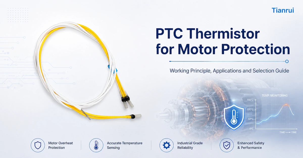
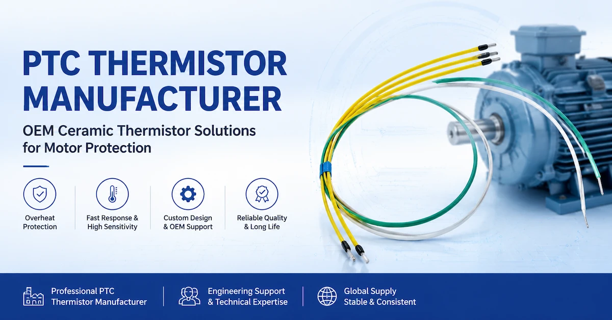
Tianrui offers a motor-specific product identified as the 3 Core Triple Sensor MZ6 Type PTC Thermistor for Electric Motor Protection.
The product is intended for winding temperature monitoring and related motor overtemperature protection applications.
Tianrui's published product page includes both electrical and thermal characteristics relevant to OEM selection.
MZ6 electrical and thermal specification overview
| Parameter | Published MZ6 information | OEM engineering significance |
|---|---|---|
| Product family | MZ6 Motor Protection PTC | Motor winding temperature detection |
| Rated response temperature, Tk | Available values within 60–180°C | Must match the motor's thermal design |
| Tk tolerance | ±5°C | Defines the published tolerance around the response temperature |
| Maximum working voltage | 30V | Applies to the sensor circuit, not motor power supply |
| Normal/measurement voltage | ≤2.5V | Relevant to the manufacturer's specified resistance measurements |
| Room-temperature resistance, R25 | ≤100Ω single element; ≤300Ω three-element configuration | Important for relay input compatibility |
| Resistance at Tk − 5°C | ≤550Ω single element; ≤1650Ω three-element configuration | Helps establish the lower-temperature response boundary |
| Resistance at Tk + 5°C | ≥1330Ω single element; ≥3990Ω three-element configuration | Helps assess high-temperature relay recognition |
| Published response-time value | Less than 5 seconds | Test conditions must be confirmed before use as a system-level claim |
| Published insulation-strength value | 2.5kV | Test method and applicability require confirmation |
Source: Tianrui's MZ6 Motor Protection PTC Thermistor Product Page.
The resistance values above reflect the single-element and three-element figures presented in the manufacturer's table. Because the website displays duplicated column headings, OEM customers should confirm the exact column interpretation, test conditions, and part-specific values using an approved datasheet before finalizing a design.
These figures also describe sensor characteristics, not guaranteed shutdown temperatures of a complete motor.
Understanding the resistance values
The resistance at 25°C helps establish whether the sensing circuit operates within the relay's acceptable normal range.
The resistance measured below and above Tk provides information about the switching transition.
For a three-element series assembly, the total resistance is the sum of the individual sensing elements.
This is particularly important when comparing a single-element sensor with a triple-sensor configuration.
An evaluation relay intended for one configuration may not automatically be suitable for another.
Important distinction between MZ6 product listings
Tianrui's website also contains an MZ6-named listing associated with lighting and preheating applications.
That listing describes different electrical characteristics and should not be treated as the same product as the MZ6 motor winding protection assembly.
For motor protection projects, buyers should use the product specifically identified for electric motor protection and confirm the complete manufacturer part number.
Never approve an electrical protection component based on the series name alone.
4. How to Select the Correct Tk Response Temperature
The rated response temperature, usually identified as Tk, is one of the most important parameters in motor protection thermistor selection.
It determines the temperature region in which the thermistor undergoes its characteristic resistance increase.
Selecting Tk involves balancing two requirements:
The motor must operate normally without unnecessary tripping, while protection must activate before an unacceptable thermal condition occurs.
Neither requirement can be evaluated correctly using only a nominal sensor temperature.
Step 1: Identify the motor insulation system
The motor's insulation system establishes important thermal constraints.
Common insulation-system thermal classes include Class B (130), Class F (155), and Class H (180), although the actual design requirements depend on the equipment and applicable standards.
These classifications should not be interpreted as a universal table of correct PTC switching temperatures.
For example, a Class F motor should not automatically receive a 150°C thermistor without a thermal engineering review.
The selected response temperature depends on the motor construction and where the sensor is installed.
Step 2: Review the actual winding temperature
Motor engineers should establish the winding temperature under relevant operating conditions.
These may include rated load, maximum expected ambient temperature, different duty cycles, and conditions that challenge the cooling system.
The motor's temperature distribution can vary substantially.
The temperature measured near an accessible winding location may differ from that at the hottest internal point.
This difference matters because the thermistor responds to its own local temperature.
Step 3: Account for the sensor's thermal location
Suppose a thermistor is installed in a part of the winding that runs cooler than the critical hotspot.
Even if the sensor switches at its specified temperature, the hottest winding region may already have exceeded the acceptable limit.
Conversely, placing a sensor near an external heat source unrelated to the protected winding could cause nuisance shutdowns.
The sensor position should therefore be established during motor development, rather than selected solely for assembly convenience.
Step 4: Consider operating temperature variation
Motor temperature changes with ambient conditions, load, ventilation, and duty cycle.
A pump motor operating continuously in a warm equipment room may require different thermal protection evaluation from a fan motor operating intermittently in a cooler environment.
The same insulation class does not guarantee identical operating temperatures.
Step 5: Include sensor tolerance and protection delay
The published Tk tolerance and the time taken for the sensor, relay, and control system to respond all affect the final result.
For instance, if a specified sensor has Tk = 145°C with a published tolerance of ±5°C, the manufacturing tolerance must be considered during system design.
This is an illustrative calculation based on the stated tolerance, not a recommendation that every Class F motor should use that temperature.
The final design needs to account for the motor's thermal margin and the time required for protective action.
Step 6: Validate the selected response temperature
The final Tk selection should be verified using representative motor samples.
Testing needs to demonstrate that the motor can operate within its intended conditions without nuisance trips and that the protection system responds appropriately during relevant thermal overload conditions.
An approved sensor specification is necessary, but it does not replace complete motor testing.
5. Single PTC vs Triple PTC Thermistor: Which Configuration Should Motor OEMs Choose?
Both single-element and multiple-element PTC thermistors can be used in motor protection systems, depending on the application.
The correct configuration depends on the motor's electrical arrangement, thermal distribution, available installation space, and selected protection relay.
| Selection factor | Single PTC sensor | Three-element PTC sensor assembly |
|---|---|---|
| Number of sensing elements | One | Three |
| Typical application | Localized motor or component temperature monitoring | Multiple winding locations in a three-phase motor |
| Temperature coverage | One installation location | Three selected installation locations |
| Series resistance | Individual sensor resistance | Sum of connected sensor resistances |
| Relay matching | Based on one sensor's characteristic | Based on the complete sensor chain |
| Installation complexity | Usually simpler | Requires additional placement and wiring |
| Main design risk | Missing a hotspot away from the sensor | Incorrect placement, wiring, or combined resistance |
| OEM validation | Local temperature and system response | Individual and combined sensor behavior |
When a single sensor may be suitable
A single thermistor may be considered when one measurement location is sufficient for the protection objective.
Examples may include selected small motors or equipment where the critical thermal condition is adequately represented by a particular location.
However, this must be demonstrated through thermal evaluation.
A single sensor should not be selected merely because it is less expensive.
When a triple-sensor configuration is preferable
For a three-phase induction motor, three PTC sensing elements may be placed at appropriate locations associated with the phase windings.
The elements are commonly connected in series to a suitable protection relay.
If one sensing element reaches the switching region, the total series resistance increases.
The relay can then respond to the high-resistance condition.
Why total resistance is important
Consider three sensors connected in series.
At any given temperature distribution:
Rtotal = R1 + R2 + R3
The relay reads the combined resistance of the series circuit.
If all three sensors are relatively cool, their resistances add together to form the normal sensor-circuit resistance.
If one sensor becomes hot, its resistance increase can dominate the total.
This is useful for detecting excessive heating in one monitored winding even when the other two are cooler.
However, an OEM must verify that the normal total resistance remains acceptable and that the resistance during the relevant thermal fault crosses the relay's specified trip threshold.
For Tianrui's motor protection range, the published three-element resistance values provide a useful starting point for this compatibility review.
6. How to Match a Motor Protection Thermistor With a PTC Relay
Choosing the correct thermistor is only one part of the protection design.
The relay or electronic evaluation circuit must recognize the sensor's resistance characteristics and initiate the required response.
This interface is a frequent source of compatibility problems when buyers replace an existing sensor with another manufacturer's component.
Understanding the sensor input
A PTC motor protection relay normally applies an appropriate measurement signal to the thermistor circuit.
It measures or evaluates the resistance and determines whether the monitored condition is normal or requires protective action.
The precise measurement voltage, trip threshold, reset threshold, and fault-detection functions vary with the relay model.
They should never be assumed from the general description "PTC relay."
Four compatibility checks
1. Normal-state resistance
The complete sensor circuit must remain within the relay's acceptable resistance range during normal operation.
For a three-element series arrangement, this means checking the sum of the sensor resistances, not just the value of one element.
2. Trip-state resistance
When the selected sensing element reaches its response-temperature region, the relay should recognize the increased resistance.
A compatible relay needs a trip threshold appropriate for the thermistor's specified behavior.
3. Reset behavior
The relay's reset threshold and logic must be consistent with the sensor's cooling characteristics and the desired restart policy.
A motor may cool below the thermistor's switching region before the relay permits a reset.
4. Sensor circuit fault detection
Some evaluation relays can distinguish overtemperature, open-circuit, and short-circuit conditions.
Others have more limited diagnostic functions.
The OEM should verify which fault conditions the selected relay detects and how it responds.
Why the sensor voltage rating must not be confused with motor voltage
Tianrui's motor protection PTC product page lists a maximum working voltage of 30V for the sensor.
This does not mean the motor itself is limited to 30V.
The sensor is part of the low-energy protection circuit and is electrically distinct from the main motor power circuit.
For example, a motor may operate from a three-phase industrial supply while the thermistor is monitored through a separate, appropriately designed relay circuit.
The specific isolation and insulation requirements must still be verified for the complete application.
Do not connect a low-voltage PTC sensor directly across a motor power supply unless the approved circuit design explicitly permits it.
Example of a relay compatibility review
An OEM evaluating a three-element MZ6 assembly should request:
-
Resistance values for the complete series assembly at specified temperatures.
-
Measurement conditions used for the resistance data.
-
Relay input measurement voltage or current.
-
Relay trip and reset resistance thresholds.
-
Open-circuit and short-circuit diagnostic behavior.
-
Permitted number of connected sensing elements.
-
Applicable lead resistance and wiring limitations.
-
Required shutdown and restart logic.
Only after these points have been checked should the engineer approve the sensor and relay combination.
7. Where Should a Motor Protection Thermistor Be Installed?
Installation affects the temperature that the sensor detects.
The best sensor location is not necessarily the easiest place to insert a component during motor assembly.
The objective is to monitor a temperature that accurately represents the critical thermal condition of the protected winding.
Stator winding installation
In many three-phase motors, PTC sensing elements are positioned within or close to the stator winding assembly.
This enables them to follow winding temperature changes more directly than a sensor mounted on the outer motor housing.
However, the precise location depends on winding geometry, insulation structure, and the motor's thermal profile.
A position suitable for one motor frame or winding configuration may not be suitable for another.
Avoid excessive mechanical stress
Thermistors and their lead connections can be damaged during winding insertion, insulation work, and assembly.
Tianrui's motor protection product instructions emphasize avoiding excessive pressure on the sensing region and excessive pulling force on the leads.
OEM assembly procedures should therefore define how the sensor is positioned, how the leads are routed, and how mechanical strain is controlled.
Confirm electrical insulation
The sensor circuit must be appropriately insulated from the motor winding and other conductive parts according to the applicable design requirements.
The published insulation-strength information for an individual component should not be treated as proof that the completed motor assembly meets its required insulation tests.
Wire insulation, lead routing, connection points, and manufacturing processes all affect the finished system.
Protect the sensing function during production
A sensor can pass incoming electrical inspection and still be damaged during motor manufacturing.
For example, lead damage or an internal defect may occur during winding installation or subsequent processing.
The production process should therefore include appropriate verification after the sensor has been installed.
Verify the temperature response
A practical validation program should compare thermistor operation with independently measured motor temperature during representative tests.
The engineering team should confirm that the sensor responds early enough under relevant thermal conditions and does not cause nuisance shutdown during acceptable operation.
This should be established before committing the design to volume production.
8. Which Motors and Equipment Benefit From PTC Winding Protection?
Motor protection thermistors are relevant to many industrial applications, but the required configuration and validation depend on the machine.
Industrial induction motors
Industrial induction motors used in conveyors, production machinery, material handling equipment, and automated systems may experience variable loads and changing cooling conditions.
Winding protection thermistors can provide a direct thermal signal to the control system.
Important evaluation factors include the motor duty cycle, cooling method, ambient temperature, overload behavior, and shutdown requirements.
Pumps and pumping equipment
Pumps may operate under changing hydraulic loads or experience abnormal conditions associated with blocked impellers and mechanical faults.
These conditions can contribute to motor heating.
A suitable winding sensor can support the protection system by indicating excessive local temperature.
However, it does not replace dry-run detection, pressure monitoring, or other pump-specific safeguards where those functions are needed.
Fans and ventilation systems
Motor cooling can depend on airflow conditions.
A fan motor operating under restricted ventilation or at certain reduced-speed conditions may experience elevated temperature.
Thermistor selection should account for the motor's cooling arrangement and operating profile.
For variable-speed applications, the OEM must also evaluate the drive configuration and how its protection inputs interface with the thermistor system.
Compressors
Compressors can encounter demanding thermal conditions associated with starts, operating pressure, ambient temperature, and cooling effectiveness.
Winding temperature monitoring may contribute to motor protection.
However, compressor protection systems also require consideration of starting conditions, refrigerant and lubrication-related constraints, and application-specific controls.
A motor protection thermistor should not be confused with a motor starting PTC.
Tianrui maintains a separate Motor Starting PTC Thermistor product listing for starting-circuit applications.
Industrial automation equipment
OEM machinery builders may integrate winding temperature protection into motor control panels or programmable control systems.
The thermistor relay can supply a protective status signal to the relevant control equipment.
Where machinery safety is involved, the complete shutdown architecture must be developed according to the applicable equipment requirements.
The sensor itself does not establish a complete machine safety function.
9. Motor Protection Thermistor vs Other Motor Protection Methods
PTC winding protection is most useful when its capabilities and limitations are understood.
A good motor design may employ several complementary protection methods.
| Protection method | What it monitors | Main strength | Important limitation |
|---|---|---|---|
| PTC winding thermistor | Local winding temperature threshold | Direct thermal indication from selected winding location | Requires relay/controller and suitable thermal placement |
| Current overload relay | Motor current and modeled overload conditions | Detects many sustained overload scenarios | Does not directly measure winding hotspot temperature |
| RTD sensor | Temperature through a calibrated resistance relationship | Supports continuous temperature measurement | Requires compatible measurement electronics |
| NTC temperature sensor | Temperature through decreasing resistance | Useful for continuous sensing and control | Requires appropriate calibration and control logic |
| Thermal switch | Temperature at its installation point | Can provide a defined switching action | Switching accuracy and application limitations depend on device |
| Motor drive thermal model | Estimated thermal condition from operating inputs | Can integrate operating information | Accuracy depends on model assumptions and inputs |
When PTC protection is preferable
PTC winding thermistors can be useful when the primary requirement is to detect a defined winding temperature threshold.
A compatible PTC relay can provide a straightforward interface for initiating an overtemperature protective action.
When continuous temperature measurement is required
If the OEM needs to continuously measure and display winding temperature, or use temperature as a control variable, an RTD or another calibrated sensing technology may be more appropriate.
A switching PTC is not generally intended to provide accurate continuous temperature readings over a broad range.
Why combined protection may be necessary
Current monitoring, temperature monitoring, short-circuit protection, and equipment-specific fault detection address different problems.
For example, a rapid electrical fault may require a protective device that acts faster than a thermally responsive winding sensor.
Conversely, reduced ventilation may produce elevated winding temperature without the same response from current-based protection.
The complete motor protection strategy should cover the foreseeable failure conditions, not rely on one component for every hazard.
10. What Testing Should Be Completed Before OEM Production?
A successful prototype does not automatically demonstrate reliable performance in production motors.
OEM manufacturers need to confirm that the selected motor protection thermistor satisfies the electrical, thermal, mechanical, and system-level requirements.
A practical validation plan should distinguish component tests from complete motor tests.
Component-level evaluation
| Test | Main purpose | Acceptance basis |
|---|---|---|
| R25 measurement | Confirm room-temperature resistance | Approved part-specific limits |
| Response-temperature test | Verify specified Tk behavior | Approved temperature tolerance |
| Resistance-temperature test | Check resistance near Tk | Manufacturer's specified resistance limits |
| Lead and connection inspection | Detect physical defects | Approved drawings and workmanship criteria |
| Insulation verification | Evaluate applicable dielectric requirements | Defined test method and limits |
| Sensor response evaluation | Examine thermal response behavior | Agreed measurement conditions |
| Environmental testing | Evaluate relevant thermal or mechanical stress | Project-specific test plan |
Motor-level evaluation
After the sensor is installed in the motor, additional tests may be necessary.
Normal-load thermal test: Confirm that the motor operates within its permitted temperature limits and that the thermistor does not cause unnecessary shutdown.
Thermal overload evaluation: Verify that the protection system responds appropriately as winding temperature approaches the unacceptable operating region.
Cooling and restart test: Check how the sensor and control system behave after the motor cools, including any required reset action.
Sensor wiring fault test: Determine the system response to a disconnected or shorted sensor circuit, where those conditions are relevant to the design.
Production assembly verification: Confirm that installation has not damaged the sensing elements or their connections.
Tests involving locked rotors or severe overloads can damage equipment and create hazards. They should only be carried out under an engineered test procedure using appropriate facilities and safety measures.
Applicable standards and documentation
IEC 60034-11:2020, Rotating Electrical Machines — Part 11: Thermal Protection, provides requirements relating to certain thermal protectors and detectors used in induction motors.
Its scope includes specified single-speed, three-phase cage induction motors using direct-on-line or star-delta starting, with rated voltages up to 1,000V.
This scope should not be extended automatically to every motor type or variable-speed application.
DIN 44081 and DIN 44082 are also relevant reference standards for applicable PTC thermistor sensor configurations.
For any claimed compliance, the buyer should verify the correct standard, edition, product configuration, and supporting documentation.
Reference to a standard does not establish that every Tianrui product or completed motor has been independently certified to that standard.
The product manufacturer and motor OEM should agree on the applicable requirements before approving the protection design.
11. How to Reduce Production and Procurement Risks
For an OEM buyer, the purchasing process should connect engineering approval with production controls.
Several risks become especially important when motor protection thermistors are purchased in recurring quantities.
Risk 1: Selecting by product name alone
Different components may share similar PTC or MZ family descriptions while serving different applications.
Recommended action: Identify the exact motor protection model and approve its complete electrical and mechanical specification.
Risk 2: Using an unverified relay
A sensor may have an acceptable switching temperature but be incompatible with the selected evaluation relay.
Recommended action: Compare the resistance characteristics of the entire sensing circuit with the relay's documented thresholds.
Risk 3: Assuming the insulation class determines Tk
Insulation-system classification is important, but it does not independently establish the correct thermistor response temperature.
Recommended action: Use motor temperature measurements and applicable thermal protection requirements.
Risk 4: Insufficient installation validation
A correctly specified sensor installed at the wrong location may respond too late or may not represent the critical winding temperature.
Recommended action: Validate the installation in representative completed motors.
Risk 5: Inconsistent production documentation
If engineering approves a sample but purchasing orders a loosely described component, later shipments may not match the original design intent.
Recommended action: Use an approved part number, controlled specification, drawings, and agreed acceptance criteria.
Risk 6: Overlooking lead and insulation construction
The electrical sensor characteristics may be correct while the selected lead configuration or insulation is unsuitable for motor assembly.
Recommended action: Review the full installed sensor construction, not only its ceramic sensing element.
Risk 7: Ignoring change management
Changes to the sensing element, leads, insulation, or manufacturing process may affect fit or performance.
Recommended action: Establish which modifications require customer notification and reapproval.
These controls are particularly important for manufacturers producing the same motor model over extended periods.
12. OEM Custom Motor Protection Thermistor: What Can Be Specified?
Industrial motor manufacturers may require more than a standard thermistor element.
The application can involve particular response temperatures, sensor arrangements, lead lengths, insulation constructions, or installation constraints.
Tianrui presents its PTC thermistor manufacturing operations as supporting engineering requirements and custom component development.
The suitability of individual customization requests must be confirmed before commercial approval.
Response-temperature requirements
A motor OEM may need a particular rated response-temperature value within the manufacturer's supported series.
The specified Tk should come from the motor's thermal design and test requirements.
Buyers should provide the target temperature, tolerance requirements, and relevant operating conditions.
Single or triple-sensor configuration
The OEM should define whether the project requires an individual sensing element or a multi-element assembly.
For three-element designs, the connection arrangement and combined electrical characteristics must be clearly documented.
Lead-wire configuration
Wire length, connection arrangement, insulation, and routing requirements can affect motor assembly.
The manufacturer should confirm the proposed construction and its feasibility under the relevant manufacturing and operating conditions.
Mechanical integration
Available winding space, sensor dimensions, and mounting constraints may influence component selection.
Providing motor drawings or sample assemblies can help identify potential installation problems before production.
Quality and documentation requirements
OEM projects may require resistance test records, approved technical drawings, incoming inspection criteria, and traceability arrangements.
The availability of specific documentation should be established during the project review rather than assumed.
From sample development to volume supply
A practical qualification sequence is:
-
Submit the motor application and electrical requirements.
-
Confirm the proposed sensor and response temperature.
-
Review relay compatibility and installation requirements.
-
Request representative samples.
-
Complete component and motor-level validation.
-
Approve the controlled specification.
-
Confirm production and inspection requirements.
-
Arrange volume orders under the agreed commercial terms.
This approach helps align engineering and procurement decisions.
To discuss application-specific configurations, visit Tianrui's OEM Motor Protection Thermistor Inquiry Page.
13. What Should OEM Buyers Include in a Motor Protection Thermistor RFQ?
A clear request for quotation can shorten technical clarification and reduce the risk of selecting an unsuitable product.
For motor protection applications, the inquiry should describe the complete use case rather than only the nominal component resistance.
| RFQ information | What the buyer should provide |
|---|---|
| Motor type | Three-phase induction motor, compressor motor, pump motor, or other design |
| Motor rating | Rated voltage, power, frequency, and duty information |
| Insulation system | Relevant thermal class and design requirements |
| Response temperature | Required Tk or thermal performance target |
| Sensor arrangement | Single PTC or three-element sensor assembly |
| Electrical characteristics | Required resistance values and tolerance |
| Protection relay | Manufacturer, model, and sensor input characteristics |
| Installation | Proposed winding location and available space |
| Construction | Lead-wire, insulation, dimensions, and connection requirements |
| Environmental conditions | Ambient temperature, thermal cycling, vibration, and moisture exposure |
| Validation | Required electrical, thermal, insulation, and assembly tests |
| Commercial requirements | Sample quantity, initial order, forecast annual demand, and project schedule |
Example OEM inquiry
Project: Three-phase industrial motor winding overtemperature protection
Application: Motor protection using an embedded PTC sensor assembly
Preferred family: Tianrui MZ6 Motor Protection PTC
Sensor arrangement: Three sensing elements connected to a compatible evaluation relay
Target Tk: To be finalized after motor thermal design review
Important requirements: Relay compatibility, lead configuration, winding installation, insulation, and defined thermal response
Requested documentation: Product datasheet, resistance-temperature limits, dimensional drawing, relevant test information, and sample availability
Commercial information: Planned prototype quantity, estimated annual demand, and target project schedule
This level of information enables the supplier to discuss the actual engineering requirements rather than quoting an insufficiently specified component.
14. How to Evaluate a Motor Protection Thermistor Manufacturer
Selecting a manufacturing partner is not simply a question of obtaining the lowest component price.
A suitable supplier should be able to explain the product's function, clarify its electrical characteristics, and support the OEM's qualification process.
Product specialization
The supplier should distinguish motor winding protection thermistors from motor starting PTC devices and general overcurrent-limiting components.
Similar terminology should not result in different technologies being offered as direct substitutes.
Technical documentation
The OEM should be able to obtain suitable part-specific information for the proposed product.
For winding protection applications, this commonly includes Tk, resistance limits, construction details, and relevant measurement conditions.
Quality control
The manufacturer should explain how relevant electrical and physical characteristics are checked during production.
Where quality assurance requirements are critical, buyers should request supporting documentation and agree on the applicable inspection plan.
Sample evaluation
The ability to supply samples for motor-level testing is important.
Samples should be representative of the construction that will be approved for production.
Manufacturing consistency
Reliable long-term sourcing depends on the ability to reproduce the approved component characteristics.
Purchasing teams should consider production controls, inspection arrangements, change management, and communication when evaluating suppliers.
Tianrui Electronics manufacturing background
Dongguan Tianrui Electronics Co., Ltd. is a China-based manufacturer founded in 2010, specializing in PTC thermistor components and related temperature-control products.
The company reports a 5,000-square-meter facility in Dongguan, automated manufacturing equipment, and specialized testing instruments.
Its product range includes motor protection PTC thermistors, other PTC protection components, PTC heating elements, and temperature-sensing products.
For motor OEM buyers, the relevant next step is to review the specific motor protection thermistor requirements and confirm component suitability through documentation, sampling, and engineering testing.
15. Frequently Asked Questions About Motor Protection Thermistors
What is the purpose of a motor protection thermistor?
A motor protection thermistor detects temperature changes within or near a motor winding. A switching-type PTC sensor increases resistance sharply when it reaches its rated response-temperature region. A compatible relay or control circuit detects the resistance change and initiates the required protection response.
Is a motor protection thermistor the same as a motor starting PTC?
No. A motor protection thermistor monitors winding temperature and works with a protection circuit. A motor starting PTC is used in an appropriate starting circuit to change auxiliary-winding current through self-heating. The two applications require different electrical and thermal characteristics.
What does Tk mean on a motor protection PTC?
Tk is the rated response temperature associated with the thermistor's characteristic resistance transition. The correct Tk depends on the motor's thermal design, sensor placement, insulation requirements, and the behavior of the complete protection system.
How many PTC thermistors are needed for a three-phase motor?
A three-sensor arrangement is commonly used to monitor selected locations associated with the three phase windings. However, the correct number depends on the motor's construction, thermal behavior, and required protection coverage. The sensing arrangement should be validated during motor development.
Can three PTC thermistors be connected in series?
Yes, appropriately specified sensors can be connected in series and monitored by a compatible motor protection relay. The combined resistance characteristics must match the relay's normal, trip, and reset requirements.
Does a PTC thermistor directly disconnect the motor?
A typical winding protection PTC does not directly switch the main motor current. It provides a temperature-dependent resistance signal to an evaluation relay or controller, which initiates the motor's protective action.
Can the MZ6 sensor be connected directly to a 400V motor supply?
The motor protection MZ6 product page lists a maximum sensor working voltage of 30V. The thermistor is intended for the appropriate sensor-monitoring circuit, not direct connection across the motor's high-voltage power supply. The circuit must be designed according to the applicable electrical and insulation requirements.
Can a Class F motor use a 150°C PTC thermistor?
A nominal Class F insulation system alone is insufficient to confirm the correct sensor response temperature. The motor's actual winding temperature, hotspot distribution, operating conditions, and thermal protection requirements must be reviewed before selecting Tk.
Does a motor protection thermistor replace an overload relay?
Not necessarily. A PTC winding thermistor provides temperature information from its installation location. Current overload protection, short-circuit protection, and other protective functions may still be required. The overall motor protection architecture must be evaluated.
What should be tested before approving a custom motor protection thermistor?
Relevant tests include room-temperature resistance, resistance near Tk, relay compatibility, installation integrity, insulation requirements, normal-load thermal performance, and protection response under representative abnormal conditions. Acceptance criteria should be agreed upon before production approval.
16. Conclusion
Choosing the correct Motor Protection Thermistor requires matching the sensor to the motor's thermal behavior and the protection relay's electrical characteristics.
For three-phase OEM motors, the most important selection factors are:
-
Rated response temperature (Tk): Select according to the motor's thermal design, not insulation class alone.
-
Sensor configuration: Choose single or triple PTC arrangements based on required winding coverage.
-
Relay compatibility: Verify normal resistance, trip thresholds, reset behavior, and sensor-circuit fault detection.
-
Winding installation: Ensure proper thermal placement, mechanical protection, and insulation.
-
Quality validation: Test the sensor and complete motor protection system before volume production.
-
OEM documentation: Establish approved specifications, drawings, inspection requirements, and change controls.
Tianrui's MZ6 Motor Protection PTC Thermistor provides a relevant starting point for OEMs developing winding overtemperature protection systems. Final suitability must be established through part-specific documentation and application testing.
Explore the MZ6 Motor Protection PTC Thermistor to review the published product information.
For custom configurations, sample requests, and production quotations, Contact Tianrui Electronics with your motor specifications, target Tk, relay details, and expected order quantity.